CT Specifications for Outdoor Breakers: Ratio, Outputs and Controller Inputs
Tiempo de lectura: unos 18 minutos
Resumen rápido
Read the CT function and full output notation before comparing ratios: a current-output rating and a low-power voltage-output sensitivity require the corresponding controller interface.
Assess accuracy and fault performance at the actual connected burden, including the input, complete lead loop and connections; a plausible load display does not prove protection performance.
Reconcile the exact sensor/core, controller input, scaling, channel, polarity and drawing revision in a paired data sheet, with evidence and an owner for every unresolved field.
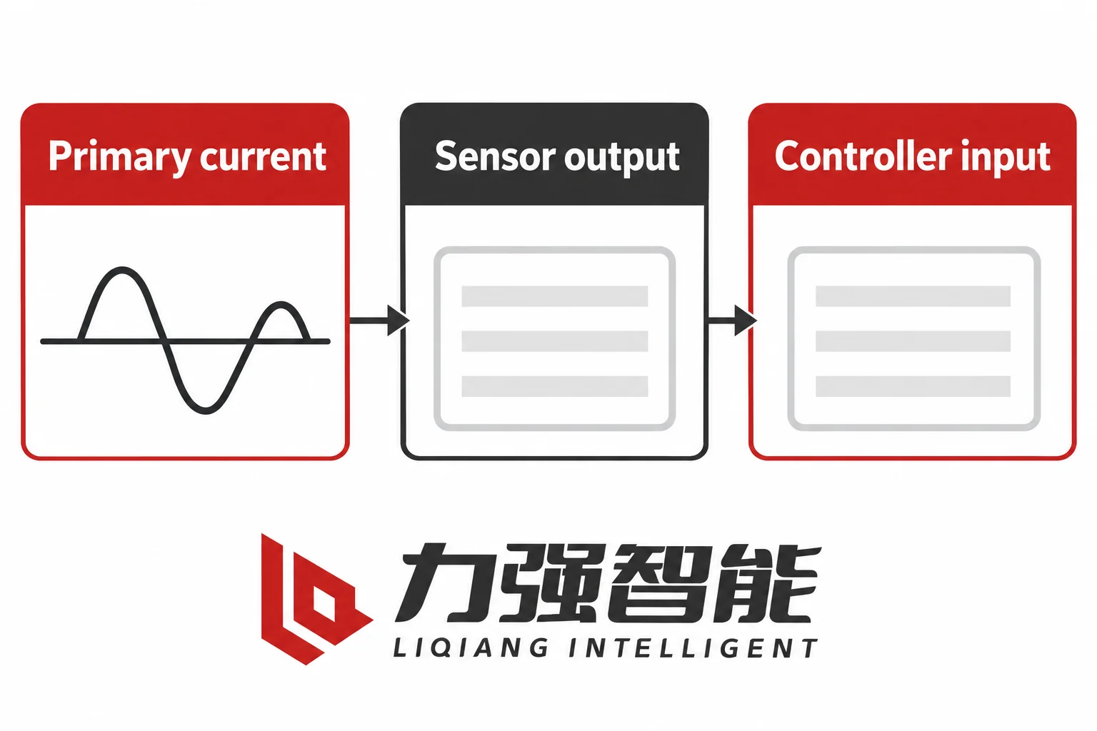
Match the current-information task, sensor output and controller input as distinct fields. This is a conceptual specification view, not an installed circuit.
A CT ratio is one field in a compatibility check, not the whole check. Before an outdoor breaker order is placed or a replacement accepted, the protection engineer needs to confirm the sensing function, the output type, the accuracy and burden conditions, and the controller input as distinct matched fields. A plausible load display shows that a value is being reported under that condition; it does not establish correct scaling, communications or fault-current performance. That distinction is the starting point for every CT-to-controller matching decision covered here.
The Current-Measurement Function: What the CT Actually Does
A current transformer or sensor converts primary-current information into a signal a controller can read. The measurement role is separate from the protection decision and the operating-energy requirement; a measurement specification alone does not establish either of those functions. Its job is accurate signal transfer across a defined range of primary conditions, into a defined load, at a defined frequency. What happens with that signal — a trip decision, a metering display, an overcurrent count — is the controller’s job, governed by its settings and firmware.
This distinction matters immediately because phase current and residual or zero-sequence current are different quantities. The scheme may derive residual current from phase inputs or use a dedicated residual sensor; identify the actual sensing and calculation path. Separate cores may have different transfer characteristics and limiting behaviour, so their assigned functions cannot be treated as interchangeable. A metering function and a protection function on the same phase may also require separate treatment, because their accuracy requirements and their operating conditions differ. A specification should name each required function and the channel or core that supplies it.
For metering, the accuracy requirement applies over the normal load region: the sensor must reproduce current faithfully across the range of currents the load will produce, into the connected burden, at the operating frequency. For protection, assess the current range, transient waveform conditions and response interval required by the actual protection method. These are different specifications, and a sensor that satisfies the metering requirement may not satisfy the protection requirement, or vice versa.
A plausible load display can coexist with an incorrect ratio setting, channel assignment or other measurement error. Even a separately verified accurate load reading does not confirm that the protection path will reproduce a fault current without distortion, that the secondary circuit will sustain the required voltage under fault conditions, or that the accuracy-limit performance needed by the protection function is actually met.
Load measurement and fault-information requirements cover different conditions. The waveform motifs are conceptual and show no actual measurement or performance limit.
The ZW20 product documentation illustrates this separation concretely. Its zero-sequence CT section describes a sensing function with a stated ratio, a primary-current region over which linearity is claimed, a rated resistive load, and an error bound at that load. It also distinguishes a higher primary current region where the secondary output is limited rather than linear. These are function-specific parameters, not universal CT specifications for the whole breaker. A separate section of the same documentation addresses the TA ratio configuration for the inrush and close-control path — a different identified function with different purpose. The two passages cannot be read as a single universal CT description, and neither can be applied to the other’s function without verification.
The ZW32-12 documentation similarly identifies CTs that can be installed to supply current outputs to an intelligent controller for analysis and overcurrent protection, and lists selectable ratio options. The controller is treated as a configurable item, not a fixed built-in. This means the controller’s current-input type, rated input range, channel use, and software scaling settings must each be confirmed for the selected device, not assumed from the product family name.
Ratio and Output Type Are Separate Interface Fields
When you read a CT specification, the ratio notation and the output type are separate fields. A complete primary/secondary-current notation includes rated current values and units; the isolated ratio number or a copied ratio field is still insufficient to establish the complete interface match.
For a conventional current-output CT, the primary and secondary current notation identifies the rated transformation: a certain primary current produces a corresponding secondary current into the rated burden. Within its specified operating conditions, it supplies secondary current into the connected burden; it is not an ideal source with unlimited voltage capability. The 1 A and 5 A secondary designations you encounter are generic industry designations for the secondary current magnitude, not manufacturer-specific options. The controller receiving this output needs a current input — a current-rated input circuit with a defined burden impedance.
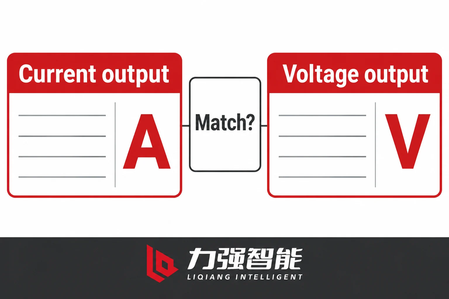
A low-power current-sensor interface may instead present a voltage signal referenced to primary current at a stated frequency, with its own sensitivity and conditioning requirements. For such a voltage-output interface, the receiving circuit needs the specified compatible voltage input. Do not infer the sensing principle or output from the term low-power alone. The ABB AdvaSense indoor sensor overview illustrates this distinction: its product overview specifies the current-sensor ratio as a primary current to voltage signal at a stated frequency, showing an ampere-to-voltage notation rather than the ampere-to-ampere notation of a conventional CT. The compatible IEDs are those with supported LPIT inputs. A connector that physically fits does not make the input compatible; the input type must match the output type.
Check the electrical output type against the supported controller input. Output type is not a distinction between sine and square waveforms.
This means a numeric scale factor entered into software cannot bridge the gap between a current-output sensor and a voltage-input circuit, or vice versa. The electrical interface must match before software scaling can do anything useful. A physically fitting plug between two incompatible interface types does not create a valid signal path. If a replacement breaker arrives with a different sensor family from the original, the controller input type must be confirmed against the replacement’s output before the installation is accepted.
The ZW20 and ZW32-12 manual descriptions use primary/secondary-current notation for the identified CT functions. Match that stated current output to the specified current input in the corresponding circuit. It does not establish that every outdoor breaker configuration uses the same output type, and it does not provide the detailed controller input rating, burden impedance, or accuracy-limit data that a full compatibility check requires.
Accuracy, Burden, and Fault Performance Must Be Specified Together
A CT ratio defines the transformation at the rated point. Whether the sensor actually achieves that transformation — and how far it departs under other conditions — depends on the accuracy specification, the connected burden, and the fault conditions relevant to the protection function.
For a conventional current-output CT, accuracy is defined over a stated current range, a stated burden, and a stated frequency. Remove any of those conditions and the accuracy statement no longer applies. The connected burden includes the controller input and the actual secondary lead and connection contributions. Include the complete outgoing and return paths applicable to the circuit, and combine their impedance or VA contributions using the specified assessment method and conditions. A cable run that was acceptable at the original installation may not be acceptable if the cable is longer in a replacement, if a different conductor size was used, or if an additional device has been inserted into the secondary circuit.
Higher loop resistance requires the CT to develop more secondary voltage to maintain the secondary current. Under demanding conditions — high fault currents, saturation onset — this increased voltage requirement can degrade the CT’s ability to reproduce the primary current accurately. The relationship between secondary burden and saturation behaviour is one of the key reasons that burden must be assessed from the actual circuit, not assumed from a nominal cable length or a universal safety margin.
For a conventional CT circuit, assess the input, complete lead loop and connections using the applicable burden method. No values or acceptance result are shown.
For protection applications, the burden assessment must extend to the fault conditions. The protection function may require the CT to reproduce current accurately at multiples of rated current that are much higher than load conditions, for a time determined by the protection relay’s operating time. A metering accuracy class alone is insufficient. Obtain the protection performance information required by the selected method, such as the applicable accuracy-limit, excitation or transient specification. These fields are alternatives or complementary requirements according to the CT and protection design, rather than a universal checklist of labels. An iron-core CT will saturate if the required secondary voltage exceeds what the core can sustain; saturation distorts the current waveform and can prevent the protection function from operating correctly or cause it to misoperate.
An air-core sensor does not have the ferromagnetic-core saturation mechanism of an iron-core CT, but its transfer path and conditioning still have limits, including usable range, linearity and frequency response. The wider term low-power does not establish an air-core construction or immunity to saturation. Identify the actual sensor principle and its limiting conditions before assessing compatibility with the protection function.
Sensor electrical withstand requirements and service conditions are also separate from controller input limits. The sensor must survive the primary-side conditions — fault current, insulation level, environmental exposure — while the controller must survive the secondary-side conditions. Both sets of requirements must be met independently.
Matching the Controller Input and Channel Definition
With the CT function identified and the output type confirmed, the next step is a paired check across all the fields that must match between the CT and the controller. Each of the following must be confirmed individually; none can be inferred from the others.
The CT or core identity and function: which specific core, what sensing principle, and which protection or metering task it is assigned to. For phase current, which phases are measured and whether all three or only two are instrumented matters for the protection functions that rely on phase-balance or residual calculations. For residual or zero-sequence current, whether the residual is derived from three phase CTs or measured by a dedicated core affects both the accuracy and the fault-current level the measurement path sees.
The current-output versus voltage or other specified signal type: confirmed against the controller’s input specification, not assumed from the connector or the ratio notation.
The rated and usable range: the CT’s rated primary current and secondary output, confirmed against the controller’s rated input range. A controller input rated for one secondary level is not automatically compatible with a different secondary level even if the ratio produces the same displayed value under load.
The controller input type, rating, impedance or burden: the specific input circuit the controller uses for each channel, including its impedance contribution to the secondary burden calculation.
Transfer or scaling settings and firmware: the software configuration that converts the secondary signal into the displayed or used current value. Software scaling can only work correctly if the electrical interface is already matched. A scaling factor that compensates for a ratio difference does not help if the signal is clipped, saturated, or the wrong type entirely.
Phase and residual channel assignment and polarity: which controller input terminal corresponds to which phase, and which direction of primary current produces which polarity of secondary signal. Phase-to-phase errors and polarity reversals can cause protection functions to miss faults or operate incorrectly, and they are not always visible as obvious anomalies under normal load.
The approved cable, connector, circuit, and drawing revision: the actual documents that describe the as-built secondary circuit, including cable sizes, run lengths, connector types, and any intermediate terminals. These must match the burden calculation.
Frequency: the CT’s specified operating frequency, confirmed against the system frequency. Low-power sensors with frequency-dependent sensitivity specifications are directly affected by this.
Schneider Electric’s UR/ADVC measurement documentation lists current-sensor signal digitization separately from auxiliary and battery monitoring. In an enquiry, identify the measurement input independently of any operating-supply field.
For a conventional CT, never open its secondary while primary current flows: hazardous voltage can result. Follow Schneider Electric’s CT guidance and the equipment procedure. Use qualified personnel and controlled verification; do not establish compatibility by live trial wiring. Other sensor outputs require their own specified handling.
Two Conditional Cases That Require Resolution Before Accepting the Match
Case 1: Same Headline Primary Rating, Different Output Family
A replacement outdoor breaker is selected to retain the existing intelligent controller. The order record carries the same primary-current entry as the original, and a headline ratio field has been copied forward without checking the output units. The match is marked as accepted on that incomplete basis.
What the check missed: the replacement unit uses a sensor from a different output family than the original. The original used a conventional current-output CT; the replacement uses a low-power voltage-output sensor. The common primary-current entry does not make the transfer specifications equivalent: one expresses current-to-current transformation, the other a current-to-voltage relationship. The selected current-input circuit cannot simply be treated as a compatible voltage-sensor input. Its electrical characteristics must match the actual sensor requirements.
The evidence needed to resolve this case: the original CT nameplate or datasheet confirming output type and secondary rating; the replacement CT or sensor specification confirming output type, transfer characteristic, and output signal type; the controller input specification confirming input type, rated range, and impedance. Reconcile the sensor’s specified output with the controller’s required input, including units, rating and usable range; these documents serve different roles and need not use identical wording.
Who owns the unresolved item: the engineer preparing the order cannot accept the match based on ratio alone. The open action is to obtain the replacement sensor’s output specification and compare it against the controller input specification before the order is released. An adapter or interposing resistor improvised at installation is not an engineered solution and should not be accepted in place of a confirmed interface match.
Case 2: Unchanged Ratio, Changed Secondary Burden
A project extends the secondary cable between the CT panel and the controller location. The existing breaker and its CTs are retained; the controller is retained; the ratio is unchanged. During normal operation after the extension, the display still shows plausible load readings. The engineer accepts the installation as compatible.
What the check missed: the longer cable has increased the total secondary loop resistance. The connected burden — controller input plus lead loop plus connections — is now higher than at the original installation. Load readings may remain plausible while the changed burden reduces the available margin for reproducing fault current. For a given secondary current, the greater loop resistance requires greater secondary voltage; whether the resulting fault performance remains adequate needs assessment. Whether the CT can still reproduce fault current adequately for the protection function depends on whether the accuracy-limit performance remains sufficient at the new burden level.
A working display under load is not evidence that the protection path is still adequate. The display reading is a metering result at normal current; fault performance at elevated current is a different operating region.
The evidence needed to resolve this case: the CT accuracy-limit or saturation data from the original CT specification; the calculated secondary burden at the original installation; the measured or calculated loop resistance at the new installation; and a comparison of the required performance against the CT’s capability at the new burden. Check any applicable controller or sensor restrictions on the connected circuit and cable, including the electrical and installation requirements in their interface documents.
Who owns the unresolved item: assign the protection assessment to a named competent engineer and allocate the CT, controller and cable-data inputs to the responsible parties. A display reading or a commissioning test at load does not close this item. The burden assessment must be completed using the actual loop and the CT’s fault-performance data.
Preparing the CT-to-Controller Data Sheet
A CT-to-controller data sheet makes the matching work explicit and keeps unresolved fields visible. The table below sets out the fields, what each side must supply, and the matching status categories.
The three status categories to use are:
Compatibility established: the particular interface field has been reconciled for the exact configuration, with the applicable calculation or verification evidence recorded. This is a field-level judgement, not a declaration that the complete installed protection system has passed commissioning.
Engineered verification pending: documents have been identified and the fields appear consistent, but the verification has not been completed (for example, a burden calculation using actual cable measurements has not yet been performed).
Incompatible: the fields disagree, or the required document has been obtained and the values do not match.
Unknown is unknown. If a document has not been obtained, the status is not “compatible pending receipt” — it is unresolved.
Field
CT/Sensor: value and document
Controller/circuit requirement
Match status
Owner / open action
Primary load/fault task and core function
Phase measurement, residual measurement, or dedicated zero-sequence; metering or protection purpose
Controller channel assignment for each function
Confirm each function has its defined sensor / derivation path and corresponding input
CT supplier and controller supplier for each channel
Ratio and output type
Primary current, secondary current or voltage sensitivity, transfer frequency
Actual supported input type, rated and usable range
Type must match before ratio scaling is relevant
Engineer: obtain sensor datasheet and controller input sheet
Accuracy and applicable burden conditions
Accuracy class or error limit, stated burden, accuracy-limit or saturation data
Required accuracy at load and at fault current levels
Assess using actual fault level and protection coordination requirements
Collect for the exact ordered combination, not for a generic family
Engineer: assemble before order release
The data sheet is useful only if it is completed for the exact ordered configuration. A data sheet completed for a generic family, an earlier model, or a similar but different ratio does not establish compatibility for the actual order. Documents collected but not compared do not constitute a verified match.
What must close before order release: CT output type confirmed against controller input type; ratio and secondary rating confirmed against controller input range; applicable burden or load-and-cable assessment completed for the actual sensor/output and connected circuit using its specified method; phase and residual channel assignment confirmed from drawings.
After delivery, the approved verification plan must address the actual installed signal path, polarity/channel mapping and protection performance at its specified conditions. Select applicable checks and methods for the equipment; do not apply a generic insulation or circuit test to a connected sensor/controller interface. Record who performs and accepts that verification.
Reconcile both sides of the specification and assign unresolved fields. The icons are generic; the blank record identifies no actual product or approved match.
For configuration-specific CT and controller specification enquiries on the ZW20, contact Liqiang via the ZW20 product page. For the ZW32-12, use the Página del producto ZW32-12. To submit a paired CT and controller specification for review, use the contact page.
Preguntas frecuentes
Does a matching CT ratio on the nameplate confirm the controller interface is compatible?
No. A complete primary/secondary-current marking identifies the rated current values and units for that CT, but it does not establish the complete interface match, connected burden or required fault performance. A voltage-output sensor uses a different transfer specification; the same primary-current entry or a copied headline ratio field does not make the two specifications equivalent. Ratio must be read alongside output type, rated secondary level, and the controller input specification before any of those fields can be marked as matched.
Why is a working load display not sufficient evidence that the protection interface is correct?
A plausible load display can be present even with an incorrect scaling or channel assignment. A separately verified accurate load reading establishes performance only under those checked conditions. It does not confirm that the secondary circuit can reproduce current accurately at the elevated levels a fault produces, that the CT’s accuracy-limit or saturation performance is adequate for the protection function, or that the secondary burden is within the limits required for fault conditions. Normal-load accuracy and fault-current accuracy occupy different operating regions of the CT’s transfer characteristic. A CT that meets the checked load condition may still fail to reproduce the fault current adequately for the selected protection function; a routine load display does not assess that fault-performance requirement.
What must be reassessed when a replacement breaker or a longer secondary cable is introduced?
For a replacement breaker, the CT output type must be confirmed against the retained controller input type — not just the primary ratio. If the output type or rating changes, reassess the electrical match and required scaling. A different family name alone neither proves incompatibility nor establishes a compatible interface. For a longer secondary cable, the total connected burden must be recalculated using the actual loop resistance of the new cable run, and the result must be compared against the CT’s accuracy-limit performance at that burden and at the fault current levels the protection function requires. A longer cable that keeps load readings within tolerance may still push the CT into saturation at fault currents. Neither case can be resolved by reading the display under load; both require a document-based comparison against the CT’s specification at the actual connected conditions.
Comparte tu amor
William Xiaonan Liu
William Xiaonan Liu escribe para LIQELE sobre equipos de conmutación de media tensión, entre los que se incluyen interruptores de vacío, interruptores de carga, seccionadores e interruptores de puesta a tierra. Sus artículos explican la selección de productos, las interfaces de instalación, los requisitos de funcionamiento y la documentación técnica, lo que ayuda a los fabricantes de aparamenta y a los responsables de proyectos a identificar la información necesaria para la selección de equipos y las negociaciones con los proveedores.
Disyuntores de vacío para interioresInstalación de panelesCompara las estructuras y las interfaces de los armarios.Fijo / extraíbleAparamenta para interioresDisposición con montaje en el sueloDisposición en tres posicionesDisposición centralDisyuntores de vacío para exterioresLíneas de distribuciónRevisa los sistemas de alimentación, detección y control.Cambio de alimentador / límiteDistribución en exterioresInterruptores de corte en cargaConmutación e integración en armariosCompara los sistemas de conmutación y la disposición de los armarios.Interruptor de carga por chorro de aireInterruptor de carga de vacíoDisposición de polos integradosSeccionadores y interruptores de puesta a tierraAislamiento y puesta a tierraRevisa el aislamiento, la puesta a tierra y las interfaces de funcionamiento.Seccionador de interiorSeccionador rotativo para interioresInterruptor de puesta a tierra para interioresInterruptor de vacío extraíble VS1-12 con polos integradosConjunto de interruptor automático de vacío para exteriores ZW32-12 con seccionadorConjunto de interruptor de corte de carga al vacío para interiores FZN25Conjunto de seccionador rotativo para interiores GN30-12Interruptor automático de vacío para interiores VS1-24Configuración representativa del interruptor automático para interiores ZN85-40.5Vista frontal de un interruptor de vacío para interiores de tres posiciones modelo VQL-12Interruptor de vacío VQL-24GD/630-25Configuración representativa de un interruptor de tres posiciones VQLA-12 con montaje centralConfiguración representativa del interruptor automático de vacío para exteriores ZW20Configuración representativa del interruptor de corte en carga FKN12Interruptor de corte en carga al vacío FZN64-12GDInterruptor de desconexión de carga con polo integrado VZF, vista traseraSeccionador para interiores GN19-12, vista frontalSeccionador para interiores GN27-40.5, vista frontalConfiguración representativa del interruptor de puesta a tierra para interiores JN15Gama de productosConfiguración representativaProducto destacadoVer todos los productosComéntanos cuáles son tus necesidadesDirectorio de seriesVer categoríaCategorías de productosConfiguración representativa del productoMostrar/ocultar la gama de productosNavegación principal de LIQSolicitar un presupuestoSolicita un presupuesto