PTs and Voltage Sensors for Outdoor Breakers: Measurement Is Not Auxiliary Power
Время чтения: примерно 16 минут
Краткое резюме
A PT ratio or sensor output describes a measurement interface; usable controller and mechanism power needs its own source, load and capacity check.
The documented ZW20 PT has two assigned duties. The ZW32 motor and coil supply fields alone establish neither a measurement source nor a compatible controller input.
Replacing a dual-duty PT or adding an operating load changes the voltage-side specification: record measurement and supply matches separately, including loading, revisions and an owner for each open action.
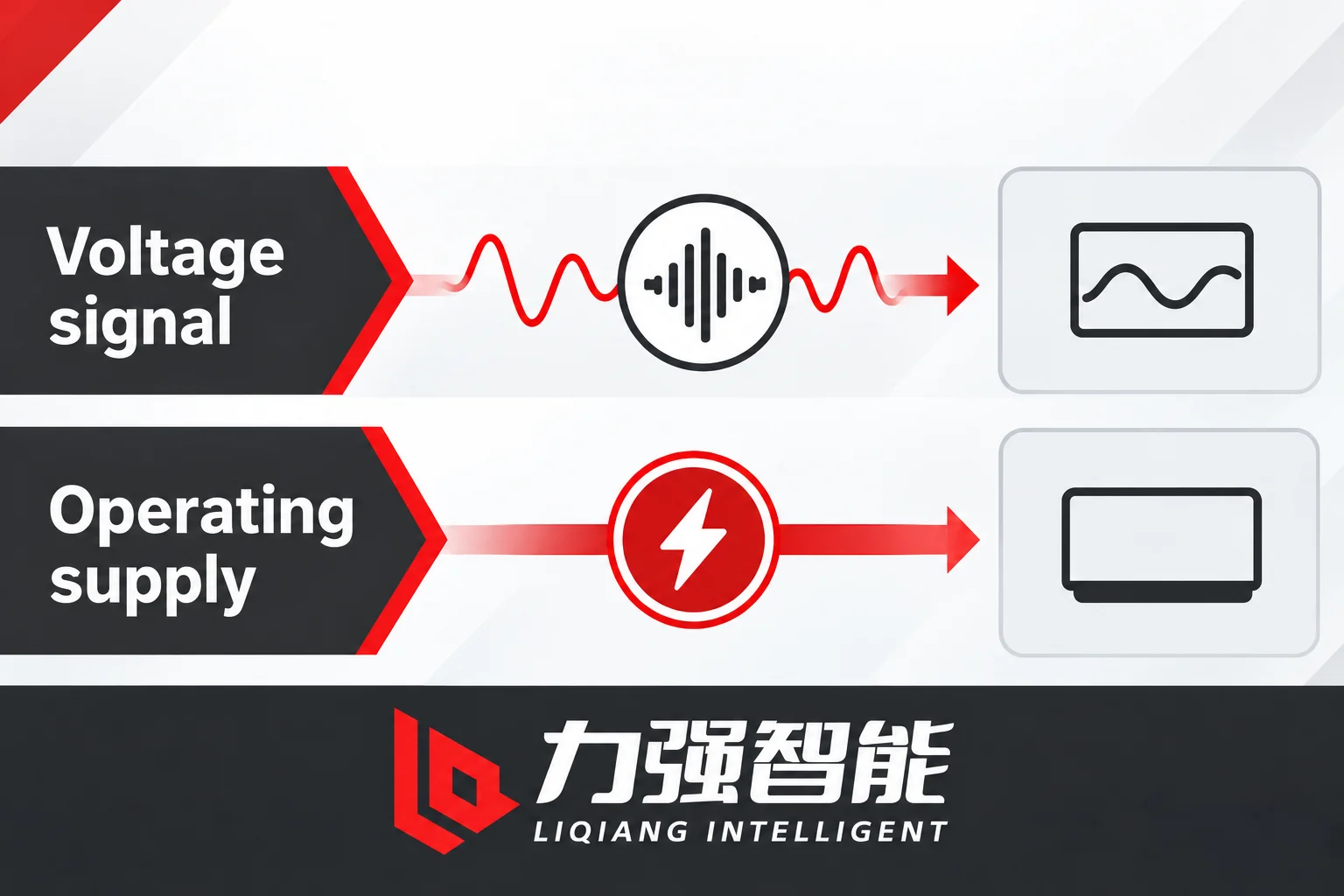
Voltage information and operating supply have different requirements. These conceptual paths do not specify separate physical sources or an installed circuit.
A voltage signal tells a controller what the primary circuit is doing. It does not automatically supply the energy the controller needs to act on that information. Specifying a PT or voltage sensor for an outdoor breaker involves two separate interface duties: measurement and operating supply. Combining them without checking both can leave a voltage-side specification incomplete. This article works through those duties, what each requires, and how to record both in a paired schedule before order acceptance.
Separate Voltage Information from Usable Operating Power
The voltage-side specification must assign two different duties, which may be served by different components. The first is to provide a scaled representation of the primary voltage with the accuracy and phase-error performance required by the selected measurement or protection function. The second is to supply enough continuous and transient energy to keep a controller alive and to operate its associated mechanisms. These are not the same job, and the components serving them are not interchangeable simply because they share a connection to the same primary conductor.
A transfer ratio describes a defined input-to-output relationship: given a stated primary voltage, the device produces a stated secondary voltage or low-level output signal under specified reference and load conditions. The ratio alone does not establish the watts or volt-amperes available to supply a controller or the selected mechanism loads. A sensor may have a precisely calibrated, stable low-level output matched to a controller’s analog input, and yet the same output may be physically incapable of sourcing the current a mechanism needs for even a fraction of a second. The voltage magnitude alone is not the question; the question is whether the source can deliver energy under the actual load, duration, and conversion conditions.
The distinction matters differently for the two products covered here.
The ZW20 documented arrangement. The ZW20-12 series documentation for one described configuration explicitly states that the external PT, located on the source side, supplies both the controller and boundary breaker operating power and the voltage signal. This is important because it means one specified component carries two assigned duties in that arrangement, and both of those duties must appear in any enquiry or acceptance record. It does not mean that every voltage sensor carries operating power capability, that the winding schedule or available burden has been verified for a specific ordered configuration, or that any other product or arrangement shares this dual-duty assignment by default. The documented arrangement is a reference point for what the ZW20 voltage-side interface requires, rather than a universal template for all outdoor breaker PTs.
The ZW32-12 load fields. The ZW32-12 documentation identifies operating voltage requirements for the charging motor, closing coil, and trip coil as separate parameter rows. These are load-side requirements; they describe what the breaker’s own mechanisms need as inputs. They do not identify or confirm what voltage measurement or operating-power source is present in any given ordered configuration. An intelligent controller is a configurable option. The motor and coil voltage fields do not establish a PT ratio, sensor output, controller input type, or approved sensor-to-controller pairing. Reading those operating voltage rows as evidence of a supplied voltage-measurement interface would be an error in specification.
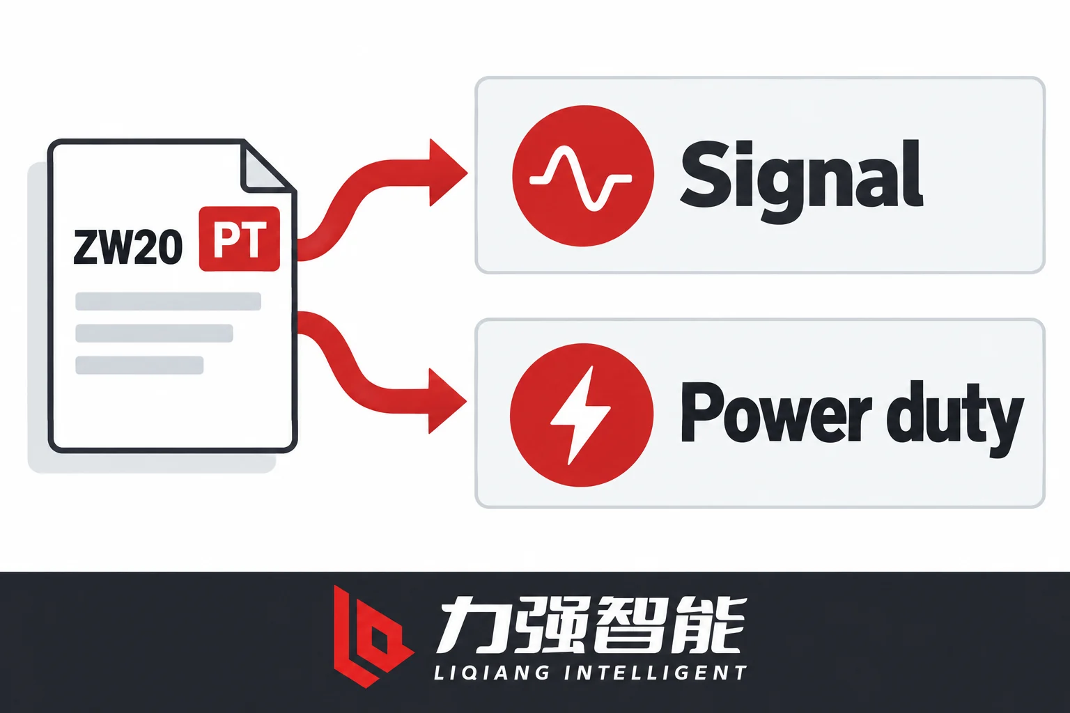
The documented ZW20 arrangement assigns both signal and power duties to its specified PT. The role diagram shows no winding arrangement and does not define every ordered variant.
The practical consequence is that these two sets of information belong in separate columns of a specification schedule. One column asks: what is the source of the voltage measurement signal, and what is its transfer, reference, and accuracy? The other asks: what is the source of operating power, what can it deliver, and what does the load require? In the ZW20 arrangement cited above, both columns may point to the same external PT, but that is a configuration fact to confirm from documentation, not an assumption to carry forward from any product with a primary winding.
Match the Measurement Reference, Transfer and Controller Input
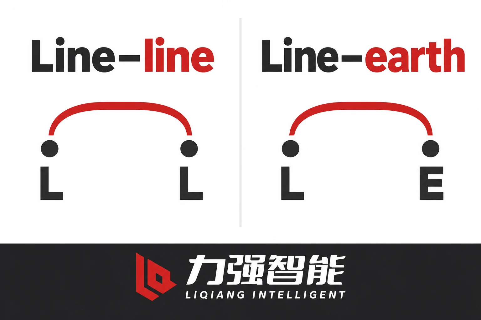
Before recording a transfer ratio, record the voltage reference to which it applies. Line-to-line and line-to-earth describe different measured quantities. The sensor or PT connection, its rated transfer, and the controller scaling must use the intended reference. A controller may display a plausible value even when these fields are inconsistent; the resulting error depends on the actual connection, device transfer and scaling. Nominal system voltage alone cannot resolve that match.
Record the actual voltage reference before comparing transfer specifications. The arcs denote measurement references, not electrical connections or test steps.
The measurement reference is therefore a specification field, not a default. The fields you need to record are:
Primary voltage basis and location: which conductors define the measured span, phase-to-phase or phase-to-earth, and which phases are measured. Also record the actual measurement point relative to the breaker and feeder, such as the specified source-side or load-side location; take that location from the selected project scheme rather than assuming a default.
Sensor or PT identity: manufacturer, model designation, and applicable configuration; for a conventional PT, the primary and secondary rated voltages with their units; for a low-power sensor, the transfer function and output type.
Frequency: the rated frequency of the measurement relationship and any dependence of accuracy on frequency deviation.
Usable range: the primary voltage range over which the stated accuracy is preserved, including conditions at the upper end that may affect regulation.
Accuracy and phase-error class: the class designation and the burden or loading condition under which it applies.
Receiving input type and impedance: the controller or relay analog input channel type, its input impedance or burden, and the voltage range it accepts.
Scaling and calibration revision: the factor applied in the controller software or hardware to convert the input signal to a displayed or processed primary voltage, and the drawing or settings revision where that is recorded.
A ratio number copied from a nameplate without its units, reference basis, or burden condition is not a complete specification. A controller input that falls within a plausible voltage range is not evidence of a correct match.
The distinction between sensor types is also relevant here. A conventional wound PT has an electromagnetic secondary whose voltage, accuracy and loading conditions must match the receiving input. A low-power voltage sensor, for example one based on voltage-divider principles, provides a specified signal output for a compatible intelligent electronic device input. As ABB’s AdvaSense product overview for indoor medium-voltage sensors illustrates, such devices use voltage-divider principles and require compatible IED input interfaces (ABB AdvaSense indoor sensors overview). A low-power sensor output is not the same signal type as a conventional PT secondary, and the two are not generally interchangeable at the controller input without confirmed compatibility between the sensor’s specified transfer and the controller’s input specification.
Schneider Electric’s UR series measurement documentation gives a separate example: its controller processes current and voltage sensor signals for measurements, while auxiliary and battery monitoring are listed separately. This illustrates distinct duties in that platform; it does not establish a LIQELE controller architecture or compatible input.
Specify Operating-Supply Duty Independently of Measurement Output
The operating-supply duty of an outdoor breaker arrangement covers a different set of questions than measurement accuracy or transfer ratio. Identify the actual receiving controller or module and the mechanism loads fitted to the selected configuration. These may include a spring-charging motor and closing or trip coils, each with its own input type and demand profile.
Assess applicable continuous, starting and shared loads against the source duty under its stated conditions. The blank ledger claims no capacity or result.
The fields you need to resolve for the operating supply are:
Input type: AC or DC, and for AC, the rated frequency.
Rated and usable voltage range: not just the nominal voltage but the acceptable band within which the receiving equipment will function correctly.
Continuous consumption: the steady-state demand of the controller and any continuously energised circuits.
Starting or short-duration demand: the starting demand of a charging motor and the short-duration demand of closing or trip coils, where those loads are fitted. These are short-duration events, but their peak magnitudes and duration requirements determine whether the source can support them without excessive voltage drop or interruption.
Power conversion and cable constraints: if the primary source is AC and the controller or mechanism needs DC, the conversion circuit’s own losses and input requirements apply. Cable impedance between source and load affects the terminal voltage available at the load under current demand.
Compare these requirements with the source’s usable output under the specified loading conditions. A VA value must be read with its stated purpose: an accuracy burden, thermal limit or operating-supply rating does not describe the same constraint. A measurement-burden rating alone does not prove that the source can supply the selected controller and mechanism loads. Nor does a VA value convert directly to usable watts without the load power factor and relevant conditions. Matching voltage magnitudes is only one part of the supply check.
ABB OVR outdoor vacuum recloser overview separately describes sensing and operating-power elements in its own arrangement. This illustrates the distinction between the two duties; it does not specify the power architecture of a LIQELE configuration.
Assess Loading, Insulation and Installation at the Actual Configuration
A conventional PT’s stated accuracy applies under its specified burden, frequency and voltage conditions. Additional operating loads may change regulation and the measurement conditions, depending on the actual winding and circuit arrangement. Do not assume either a common secondary or independent windings from a dual-duty description. Even where separate windings are documented, assess their ratings and any interaction under the manufacturer’s specified combined-load conditions; separate windings alone do not prove independent performance.
The actual winding schedule is not established from the fact that a PT is described as having dual duties. It requires the winding schedule drawing, the burden ratings for each winding, and the secondary circuit diagram. Assuming independent windings without that documentation is a specification gap, not a safe default.
For a low-power voltage sensor, check its specified receiving-input impedance, conditioning, cable and loading requirements. A conventional current-CT lead-loop burden method cannot simply be carried across to a voltage-divider interface. Use the loading model and connection conditions stated for the selected sensor and input, rather than treating every voltage measurement output as a conventional PT secondary.
The outdoor installation adds further requirements that are separate from the signal or power interface. Record the applicable primary insulation ratings, outdoor service and environmental conditions, and mounting and earthing requirements from the selected equipment documents. An outdoor label on a product and a stated primary voltage rating are starting points, not complete evidence. The secondary circuit (including any cabling between the sensor or PT and the controller) must be rated for the relevant withstand requirements and appropriate for the installation environment. These are fields to record from the selected equipment documentation for the actual ordered configuration, not extrapolations from a general product description.
Resolve Two Voltage-Side Scope Changes Before Order Acceptance
Two types of scope change commonly occur between initial specification and order acceptance, and both require re-examining the voltage-side interface before the order is treated as matched.
Case 1: Replacing a dual-duty PT with a low-power voltage sensor. Consider a project where the initial specification follows the ZW20 documented arrangement, with an external PT supplying both the voltage measurement signal and the controller and breaker operating power. If, during procurement or design development, a proposal arises to substitute a low-power voltage sensor (for a revised measurement arrangement) the substitution may satisfy the measurement interface requirement if the sensor’s output type and transfer are compatible with the controller’s input. But substituting the sensor does not carry across the operating-power duty. The PT was also the operating power source. Removing it and replacing it with a measurement-only sensor leaves the operating-power supply unassigned.
The consequence is not that the substitution is impermissible, but that it is incomplete without an identified replacement operating-power source. This source needs its own specification: input type, voltage range, and capacity under the actual controller and mechanism loads. Check the replacement operating source against the actual supply input and loads. Separately confirm the new sensor against the measurement input and scaling; the two controller interfaces must not be conflated. Any required conversion equipment also needs an explicit specification and a named interface owner before order acceptance. The documents that need updating are the equipment interface schedule, the wiring or configuration drawing, and any settings or scaling records that reference the voltage-signal source.
Case 2: Adding an operating load to an existing PT arrangement. A different scope change occurs when the PT arrangement is retained but a new load is added, such as an accessory or additional module with a documented operating demand. If the original PT was assessed against an earlier load schedule, the additional demand requires that assessment to be revisited. Depending on the winding and circuit design, the change can affect usable supply voltage, capacity and measurement conditions. Those effects need assessment against the specified loading conditions, even where no single nameplate limit appears to have been exceeded. The fact that the PT’s ratio and the system voltage are unchanged does not mean the combined arrangement is unchanged in its performance.
Before accepting an order that includes this change, compare the revised load schedule with the source ratings, winding allocation, regulation and measurement-accuracy conditions. Obtain a documented assessment or revised source proposal from the responsible supplier or project designer. Changing a winding connection or selecting a larger VA number is not, by itself, evidence that both duties are satisfied. Keep any unresolved requirement open with a named owner and the document needed to close it.
Assign an interface owner for each project. A generic note that the customer or supplier will resolve it does not identify who owns the action. The open action needs a contact, a document reference, and a defined close condition before the order is treated as fully matched.
Send a Paired Voltage-Interface and Supply-Duty Schedule
The enquiry or acceptance record for the voltage side of an outdoor breaker configuration should cover both interface duties explicitly, with separate evidence and separate open-action fields. Collecting documents is not equivalent to verifying a match; the schedule below is a framework for making the gaps visible.
Keep measurement and supply fields separate in the enquiry, then assign evidence and open actions for the exact configuration.
Функция
Selected source / output
Receiving input / load
Evidence / reference
Owner
Status / open action
Voltage measurement reference and location
PT or sensor identity, line-to-line or line-to-earth reference, phase(s), and actual measurement point relative to the breaker / feeder
Controller/relay input channel type and impedance, assigned to that measurement point
Equipment doc, approved project measurement location and configuration drawing revision
Распределить по проектам
Unknown if not documented
Measurement transfer
Ratio with units, or sensor transfer function and output level
Controller input voltage range and scaling factor
Nameplate or sensor datasheet, settings revision
Распределить по проектам
Unknown if not confirmed
Measurement frequency
Rated frequency and accuracy tolerance band
Controller/relay rated frequency
Equipment doc
Распределить по проектам
Unknown if not confirmed
Measurement accuracy and loading
Accuracy and phase-error conditions for the selected PT or sensor
Selected device documents and applicable loading assessment
Распределить по проектам
Open if relevant loading is unassessed
Operating supply: input type
AC or DC; AC frequency if applicable
Controller and mechanism input type
Equipment doc, wiring drawing
Распределить по проектам
Unknown if source not confirmed
Operating supply: voltage range
Source output voltage range under load
Controller and mechanism rated and acceptable range
Source spec, controller input spec
Распределить по проектам
Unknown if not compared
Operating supply: continuous load
Source usable continuous output
Controller continuous consumption
Source and controller docs
Распределить по проектам
Unknown if not itemised
Operating supply: starting or short-duration load
Source available output for the specified duration
Starting or coil demand where fitted to the selected mechanism
Mechanism specification and source short-duration rating
Распределить по проектам
Open if not itemised
Winding or module load allocation
Actual shared or separate outputs and their ratings
Load assigned to each output and applicable combined-load conditions
Winding or module schedule and circuit drawing
Распределить по проектам
Open without documented allocation
Insulation and service
Applicable insulation ratings and service/environmental conditions
Actual installation, circuit withstand, mounting and earthing requirements
Selected equipment and project specifications
Распределить по проектам
Open if not confirmed for the actual site
Configuration drawing revision
Drawing number and revision that governs this interface
Governing revision accepted by both parties
Approved drawing
Распределить по проектам
Unknown if drawing not issued
Settings and scaling revision
Controller settings file or relay settings revision
Consistent with above measurement transfer
Settings file reference
Распределить по проектам
Unknown if not tied to above
The “unknown” entries are not placeholders; they are open actions. Each one that cannot be closed with a document reference and a confirmed match represents a gap that should prevent the configuration from being accepted as fully specified. The test for acceptance is not whether appropriate documents exist somewhere; it is whether the specific selected values in those documents have been compared and confirmed to be consistent across source, interface, and receiving equipment for this ordered configuration.
Qualified project verification under approved procedures (commissioning measurements and functional checks as applicable) remains a separate step after documentation matching. A documented match of specification fields does not substitute for as-installed verification, and as-installed verification cannot replace a complete pre-order specification record.
For the ZW20-12 and ZW32-12 specifically, the product pages at liqele.com/products/zw20/ и liqele.com/products/zw32-12/ describe model-specific configuration choices. Confirm the selected PT or sensor, controller, operating supply and accessory scope in the actual offer. A quote must itemise these as selected components, not assume them from the base model designation. For context on the complete system boundary including recloser and switching functions, see outdoor circuit breaker versus recloser и medium-voltage switching device selection. For the current-side CT and controller interface as a parallel specification task, see outdoor breaker CT selection.
To submit a paired measurement and supply requirement schedule for an enquiry, use the contact form at liqele.com/contact/. Include the model designation, selected controller and mechanism, measurement reference and input type, and any scope changes or open actions identified at the time of enquiry.
Часто задаваемые вопросы
Does a PT with a stated transformation ratio automatically provide usable operating power for the controller and mechanisms?
No. The ratio describes a voltage relationship under its specified reference and loading conditions. It does not, by itself, establish usable supply capacity for the actual controller and mechanism. The documented ZW20 arrangement assigns both duties to a specified external PT, but an order still needs the selected output ratings, winding or module allocation, actual loads and applicable loading conditions. Check the voltage range and the required continuous or short-duration capability separately.
If a low-power voltage sensor provides the correct output voltage level for the controller’s analog input, can it replace a conventional PT without any other changes?
Not from output level alone. Confirm the sensor transfer, reference, loading conditions and scaling against the specific measurement input. If the original PT also supplied operating power, a measurement-only replacement leaves that duty unassigned unless a suitable separate source is specified. Identify its supply input, voltage range and usable capacity against the actual connected loads. Record both matches and any required configuration revision before treating the substitution as complete.
Why is the measurement reference (line-to-line versus line-to-earth) recorded as a separate specification field rather than inferred from the system nominal voltage?
The reference identifies which primary voltage the device measures. The selected connection, transfer and controller scaling must agree on that quantity; nominal system voltage does not establish their relationship. Different PTs or sensors can use different transfers, so a reference change alone does not imply a fixed change in secondary output. Record the measured conductors or reference, device transfer, receiving input and scaling revision together in the configuration schedule.
Поделитесь своей любовью
Уильям Сяонань Лю
Уильям Сяонань Лю пишет для сайта LIQELE о коммутационном оборудовании среднего напряжения, в том числе о вакуумных выключателях, выключателях под нагрузкой, разъединителях и заземляющих выключателях. В своих статьях он рассказывает о выборе продукции, требованиях к монтажу, условиях эксплуатации и технической документации, помогая производителям коммутационного оборудования и заказчикам проектов определить информацию, необходимую для подбора оборудования и переговоров с поставщиками.
Внутренние вакуумные автоматические выключателиУстановка панелейСравните конструкции и интерфейсы шкафов.Стационарный / съемныйКомнатные распределительные устройстваНапольная установкаТрехпозиционная схемаСреднее расположениеВакуумные автоматические выключатели для наружной установкиРаспределительные фидерыПроанализируйте схемы подачи, датчиков и управления.Переключение питающего источника / границыРаспределение на открытом воздухеВыключатели нагрузкиКоммутация и интеграция в шкафыСравните режимы работы выключателей и схемы размещения в шкафу.Реле нагрузки с пневматическим срабатываниемВакуумный выключатель нагрузкиРасположение встроенных полюсовРазъединители и заземляющие выключателиИзоляция и заземлениеПроверить меры по изоляции, заземлению и рабочие интерфейсы.Внутренний разъединительРотационный разъединитель для внутренней установкиВнутренний заземляющий выключательВыдвижной вакуумный выключатель VS1-12 со встроенными полюсамиУзел наружного вакуумного автоматического выключателя ZW32-12 с разъединителемКомплект вакуумного выключателя нагрузки для внутренней установки FZN25Узел поворотного внутреннего разъединителя GN30-12VS1-24 — вакуумный автоматический выключатель для установки в помещенииТиповая конфигурация автоматического выключателя ZN85-40.5 для внутренних сетейВид спереди на трехпозиционный вакуумный автоматический выключатель VQL-12 для установки в помещенииВакуумный выключатель VQL-24GD/630-25Типовая конфигурация трёхпозиционного выключателя VQLA-12 со средним расположениемТиповая конфигурация вакуумного выключателя ZW20 для наружной установкиТиповая конфигурация выключателя нагрузки FKN12Вакуумный выключатель нагрузки FZN64-12GDВыключатель нагрузки со встроенным полюсом VZF, вид сзадиВнутренний разъединитель GN19-12, вид спередиВнутренний разъединитель GN27-40.5, вид спередиТиповая конфигурация внутреннего заземляющего выключателя JN15Ассортимент продукцииТиповая конфигурацияВ центре внимания: продуктПосмотреть все товарыОбсудите свои требованияКаталог серийПросмотреть категориюКатегории товаровТиповая конфигурация продуктаПереключить ассортимент продукцииLIQ: Основная навигацияЗапросить расценкиЗапросить расценки