Совместимость запасных заглушек VCB: что нужно проверить перед заказом замены
Время чтения: примерно 19 минут
Краткое резюме
Confirm both the documented connector mating relationship and the complete position-by-position circuit mapping; matching housing or cavity count proves neither by itself.
Align the declared connector view and reference landmark without renumbering contacts, then compare function, source/common context, state and rating for every mapped position.
Keep reserved and unused positions in their documented treatment. Resolve unknowns with approved records or qualified as-built verification before confirming the replacement interface.
A matching plug body is only the first check
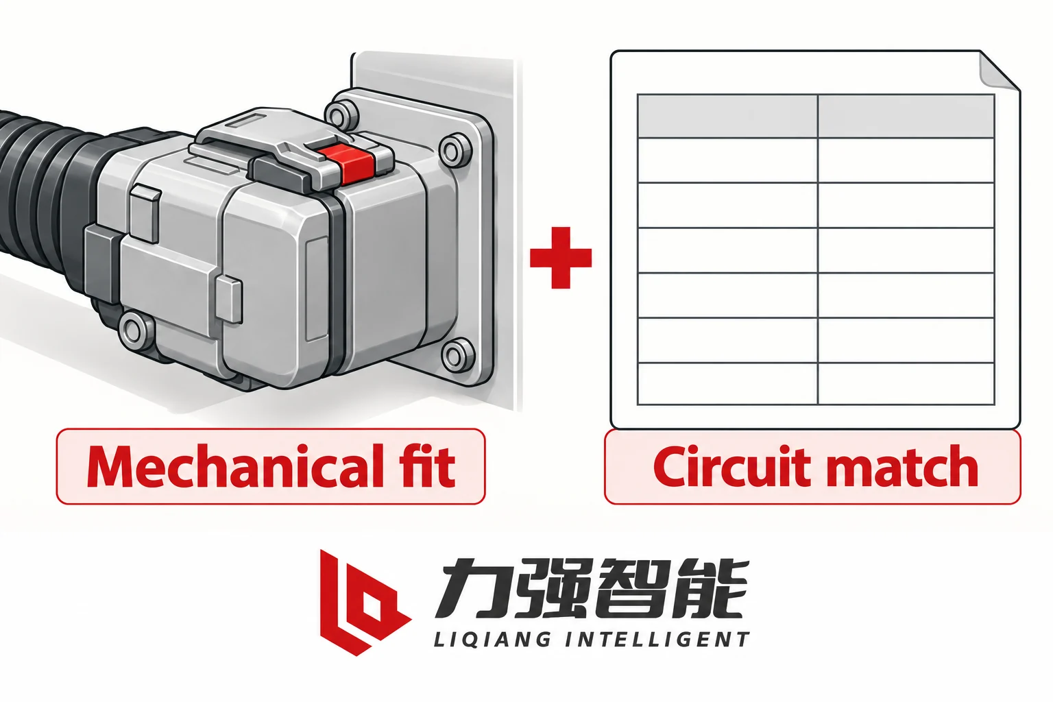
A replacement secondary plug that physically mates with the panel socket is not yet a confirmed compatible replacement. That statement is the starting point, and it cannot be shortcut. Secondary interface compatibility requires two separate agreements: the connector halves must mate mechanically, and each position must be correctly reconciled with the retained panel circuit for the proposed configuration. A housing that looks the same, carries the same number of cavities or shares a breaker family label establishes neither of those things on its own.
Mechanical mating and circuit agreement need separate checks. Generic connector concept; no product pinout is shown.
What mechanical mating actually covers
The mating interface between a VCB secondary plug and its panel socket involves several physical elements that each require separate confirmation. The housing body and insert must be geometrically compatible: the plug half must engage the socket half fully, with the documented mating shell profile and cavity layout, and suitable contact and insert specifications. The keying or polarising feature — a slot, rib, pin or shaped profile that prevents incorrect orientation — must agree between the two halves. A keying discrepancy may prevent proper engagement or remove the intended orientation protection; an apparently similar outline does not establish a mating pair.
Retention and latch are a separate question. A plug that enters a socket without resistance but does not lock is a maintenance and vibration risk regardless of the cavity alignment beneath it. Confirm that the latch or retention clip geometry and spring load are compatible with the retained panel socket, not just with the replacement breaker’s own mating half.
Confirm how each retained connector half is mounted, retained and reached by its harness. A documented mating pair can still require different mounting hardware, cable entry or harness provision. Identify any proposed change separately and obtain its approved design, rather than treating socket engagement as confirmation of the complete secondary assembly.
Finally, interface version or connector generation must be confirmed. Connector families with the same basic housing outline often evolved through generations that changed contact size, insert material, or cavity arrangement. A replacement from the same product family as the old breaker, but from a different production generation or a slightly revised connector specification, may mate partially or accept insertion with reduced retention force. Physical fit test on a bench cannot substitute for a confirmed version match against the drawing.
Photographs help identify visible features, but photographs, a product family name or a cavity count do not establish the complete mating and circuit agreement by themselves. The evidence inputs are the old panel’s secondary socket identification (drawing number, connector type designation and revision), the proposed replacement breaker’s secondary plug identification from its own documentation, and a cross-reference confirming they are a documented mating pair. Treating these as project inputs before any circuit comparison work begins avoids discovering a dimensional incompatibility after completing the functional mapping.
The VS1-12 product page directs buyers to confirm order-specific terminal assignments, wiring schedule and optional device selection; the ZN85-40.5 product page asks buyers to specify connector position, secondary-connector orientation and wiring schedule agreement before ordering. Both pages treat the secondary interface as a configuration item requiring explicit specification, not as a default that carries over from a family label.
Fix the drawing revision and the reference view
Before comparing any individual position, establish four things: the exact identity of the old breaker and panel assembly, the exact identity of the proposed replacement, which half of the connector each drawing shows, and which approved revision of each drawing is in use.
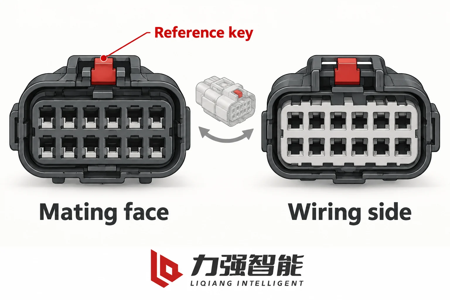
Identify the drawing view and a reference landmark before comparing positions. Generic views show no contact numbering.
Why the drawing revision matters
A secondary wiring schedule or schematic is not a timeless pinout. Manufacturers revise these drawings — to add optional devices, correct terminal assignments, add interlocks or accommodate revised secondary coupler generations. A wiring schedule from a different revision than the ordered configuration may list the same position numbers with different functions, different common groupings or different optional-device connections. The VS1 manual contains arrangement-specific secondary wiring and schematic pages with a stated mechanical condition; those pages belong to a specific arrangement and drawing revision, not to every VS1 in service. The ZN85 manual similarly carries a drawing title and revision area on its wiring pages, and its schematic note identifies a specific drawn condition: test position, spring uncharged, breaker open.
The consequence is concrete: if the old panel’s installed wiring was commissioned against revision B of the drawing and the proposed replacement’s documentation is revision D, the comparison must be made between those specific revision pairs. Using an undated copy of either drawing, or a scan that does not show the revision block, is not an acceptable substitute.
Mating face versus wiring side
A secondary connector block has two distinct views that must not be confused. The mating face is the cavity side presented to the opposing connector half during engagement — the face the panel engineer sees when inserting the plug. The wiring side is the rear face where conductors terminate into the contacts. Views from opposite sides are related by reflection, with the displayed orientation also depending on how the drawing is rotated.
If one drawing shows the connector from the mating face and the other shows it from the wiring side, the same physical position appears in a reflected location in each view. The same visual pattern of populated and empty cavities may appear to be a match when it is actually a mirror image. An apparent position-1-to-position-1 correspondence could mean two entirely different physical contacts.
The correct approach is to establish a single shared reference: both drawings must use the same declared view direction, confirmed by the view label or arrow on each drawing. Align the displayed views using their declared key or reference orientation while preserving the identifiers assigned by each approved drawing. Do not renumber contacts merely to make the patterns look alike.
A reference landmark — a keyway, a corner marker, an asymmetric cavity — serves as the anchor. When the same landmark appears in both drawings and its position in each view is consistent with the declared view direction, the numbering reference is reliable. When neither drawing carries a view direction label and no landmark is identifiable, the reference view is unresolved, and the comparison cannot proceed.
The Liqiang product manuals use arrangement-specific and state-specific drawings. There is no universal family pinout that applies to all configurations. The secondary wiring page in the VS1 documentation represents a specific arrangement — side-mounted or handcart — and declares its own schematic condition. Comparing positions between a fixed-installation panel and a handcart-type replacement using drawings from the wrong arrangement would produce an incorrect functional map even if every revision was current.
Map every position by function and circuit context
Equal cavity counts and similar connector population can create an appearance of compatibility without establishing it. Two connectors may have the same number of positions, with the same cavities populated, and still carry entirely different circuit assignments. A position number is an identifier, not a function. Do not assume that matching position numbers across products or manufacturers carry matching functions; establish the assignment from the applicable interface documentation.
Reconcile positions through function and circuit context. This blank template supplies no equipment-specific connections.
The blank per-position record
The compatibility work product is a position-by-position mapping record. Before filling any entry, the record structure defines what must be confirmed for each position. A usable blank template covers these fields:
Field
Description
Old assembly position
Position identifier as shown in the old panel’s approved wiring document
New assembly position
Corresponding position identifier in the proposed replacement’s approved document
Функция
What this position serves: close coil, trip coil A, motor supply positive, spring-charge contact, main-contact auxiliary (a or b), truck-position interlock, common/return, reserved, unused
Direction / interface role
State the reference explicitly: supply or command into the breaker, feedback to the panel, or a passive contact path with its external circuit
Source / Supply
Origin of the signal or supply (panel control bus, external relay, local auxiliary board)
Nominal voltage and polarity
As stated in the approved schematic, including polarity for DC circuits
Circuit / common context
Which common or return conductor this position shares; common/return grouping must be from the approved drawing, not assumed
Contact state reference
If this is a dry contact output: the main-contact, spring or truck-position state that determines contact condition
Contact/load rating
As documented for this position’s contact or supply path; not inferred from position count
Disposition
Documented / Reserved / Unused / Unknown
Verification status
Cross-referenced against both drawings, confirmed, or pending engineering resolution
No entry in this record may carry a function derived by inference. An old position labelled “X3” carries the function its approved schematic assigns to X3 in the commissioned revision. The new breaker’s position that appears geometrically equivalent carries the function its documentation assigns. Confirm the position pair only when its function, interface type, source/common context, state reference and relevant ratings agree with the proposed connection. If they differ, the difference is a confirmed incompatibility that must be resolved before the replacement can be ordered.
Why common and return positions cannot be assumed
A common or return position is the reference conductor for one or more active signals in the connector. Incorrectly assumed common groupings cause multiple circuits to be connected to the same return conductor when they should be separated, or to be left without a return path.
A secondary connector may carry several circuit groups, including control-load supplies, charging-motor supply, passive feedback contacts and optional control functions. Their source types and relationships depend on the selected circuit. Each of these may share a return conductor with its own circuit group, but not with the others. The return terminal for the trip coil circuit and the return terminal for the motor supply may both be labelled as commons in their respective circuits, but they must not be connected together unless the approved schematic explicitly shows a common bond.
The approved drawing defines which positions form a common group. Nothing else does. A single cable pair running to one position in the field and returning through another must be traceable to the drawing, not assumed from physical adjacency or similar wire colour.
Keep feedback, power and permission separate
A secondary connector for a medium-voltage VCB typically carries three functionally distinct categories of signal: feedback contacts that report breaker and mechanism state, power supply paths for control loads, and permission or interlock inputs that gate operations. Distinguish these roles throughout the assessment, including cases where one contact participates in both feedback and an interlock circuit.
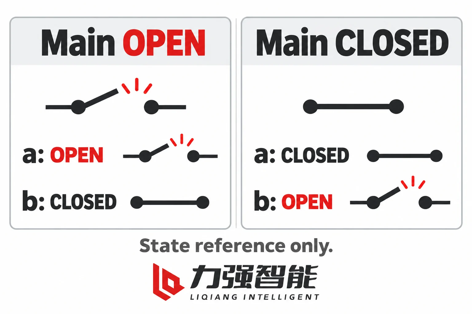
For breaker-position auxiliary contacts, a follows the main-contact state and b is complementary. State reference only; no terminals or supply circuit are assigned.
Auxiliary contact state defined against main-contact condition
The a/b designation for breaker auxiliary contacts is always defined relative to the main-contact mechanical state, not to a control command or indicator light.
An a contact follows the closed main-contact state. It is closed when the breaker main contacts are closed, and open when the main contacts are open. The Schneider Masterclad documentation illustrates this with its Type-a trip-path stages, which are open when the breaker main contacts are open — meaning an a contact in a trip circuit does not complete that path until the breaker has closed. An a contact is therefore used where the circuit needs confirmation that the breaker is in the closed position.
A b contact is the complement. It is closed when the main contacts are open, and opens when the main contacts close. A b contact may interrupt a closing-coil path when the breaker closes. Preventing repeated operations under a sustained command depends on the complete approved anti-pumping arrangement, not on the b designation alone.
This is purely a mechanical reference, not an electrical polarity. The a/b designation describes the stated breaker-state relationship; it is not a connector position or a supply polarity. Confirm which documented terminals provide that relationship in the selected assembly.
Spring, truck position and permission signals are different state questions
The spring-charge contact reports whether the closing spring has reached the charged condition, not whether the breaker main contacts are open or closed. A breaker may be in the open position with the spring charged, or in the open position with the spring discharged, and the main-contact auxiliary contact reports the same state in both cases. Confusing these two contacts can produce an incorrect indication or permission condition even when the main-contact a/b mapping appears correct.
A truck-position contact reports a different state variable: the carriage location defined by the selected panel arrangement. Its relationship to main-contact state, spring status and permitted operations comes from the actual interlock design; do not infer the permitted operations from a position label alone. These contacts carry their own position in the secondary connector and must be mapped separately.
Where the panel supplies an external permission signal, identify it as an input with its documented source and circuit context. Other permissive conditions may be implemented within the breaker or cubicle. Distinguishing an inward permission signal from an outward feedback contact matters because the direction, source voltage and return path are different. A position that appears populated on both the old and new connector may be an output on one and an input on the other, which is a fundamental incompatibility.
Voltage-free contact versus voltage-fed indication
A dry or voltage-free contact output from the breaker presents a simple make/break element. The panel’s external circuit provides the supply voltage and return, and the breaker auxiliary contact element opens or closes that path. The contact’s suitability for the circuit is governed by its rated make/carry/break capacity for the specific load: contact rating values must come from the product documentation for that contact, not from the connector cavity count or overall breaker rating.
A voltage-fed indication is different. Some secondary interface positions carry an internally sourced voltage that the external circuit reads as a logic input. Its defined signal levels, state meanings and loss-of-supply behaviour must be documented; absence of voltage does not automatically prove the opposite mechanical state. The panel circuit that accepts this input must be compatible with the source voltage, polarity and source impedance. A mismatch between passive-contact and voltage-fed interfaces can cause incorrect indication, unintended operation or equipment damage, depending on the connected circuits.
The circuit on both sides of each position — not the generic function label — determines which type is required and which is offered. For the control supply paths themselves (trip coil, close coil, motor), the article on VCB control voltage requirements covers supply identity, load conditions and component-requirement comparison; that discussion is not repeated here.
Close unknowns without inventing spare-pin functions
Consider a conditional panel-refurbishment scenario. The withdrawn old breaker and the proposed replacement appear to use the same connector family. The housing fits; the keying seems to match. The procurement engineer has the old panel’s wiring schedule and the new breaker’s wiring pages. Working through the record position by position, most entries cross-reference cleanly: close coil, trip coil, motor supply, main-contact a and b auxiliaries, spring-charge contact. But two positions present a problem.
One position appears populated on the old connector and is shown in the old drawing as a feedback signal, but the new breaker’s documentation for the same position number shows it as reserved. A second position is populated on the new breaker’s connector but is not shown in the retained panel drawing at all — it is a position the old breaker did not use.
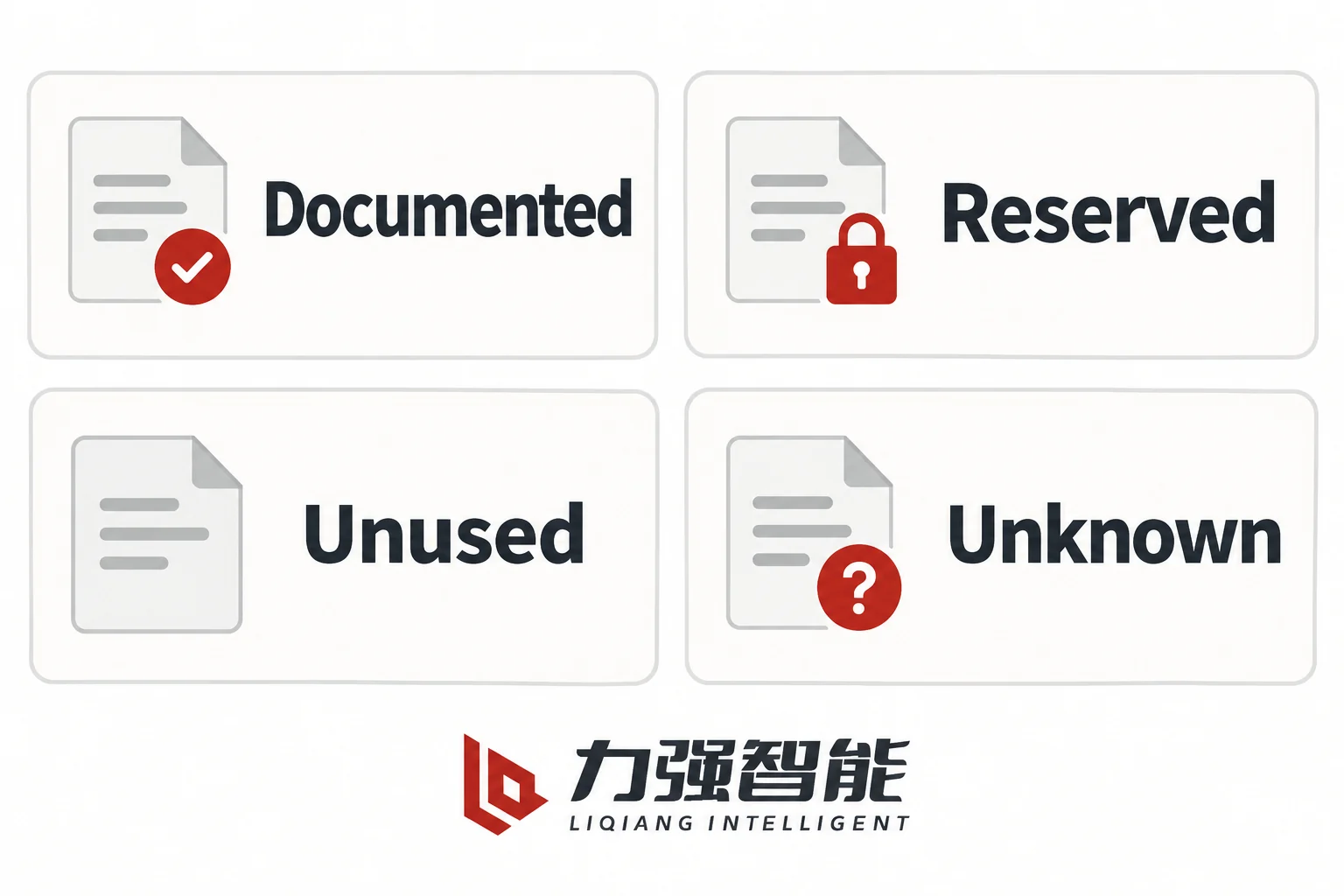
Keep documented dispositions distinct from unresolved positions. The icons indicate record status, not an electrical contact state.
Classify explicitly; do not infer
The correct disposition for each of these positions is to classify it explicitly and record the classification. The options are:
Documented — the old and new approved records confirm the function, interface type, source, common or return reference, state and relevant ratings for the proposed connection. Close the entry only when those details agree with the intended connection.
Reserved — the applicable documentation allocates or restricts this position. Preserve its stated assignment and connection treatment. Do not add a field connection or reassign it without an approved circuit revision; the word reserved alone does not establish that the contact is empty, unenergised or associated with a particular optional device.
Unused — the approved record states that this position has no used function in the ordered interface. It may be an empty cavity or a fitted but unused contact; retain the documented treatment. Neither an empty-looking cavity nor a missing entry is sufficient evidence for this classification.
Unknown — the position exists, may be populated, but its function cannot be confirmed from the available drawings. This is the outcome when a drawing revision does not cover the installed configuration, when a drawing is missing, or when the available documentation conflicts.
A position classified as Unknown blocks a compatibility conclusion for the interface. It does not become a spare, a test point or an available terminal by default.
Missing drawings are a stop condition, not a prompt to guess
Optional releases and auxiliary functions can change a control scheme. Compare the selected scheme and fitted option set, rather than using another variant as evidence of the current assignments. Without the correct version of the documentation for the actual fitted configuration, a position that appears to carry a close coil return in one configuration may serve an entirely different function in another.
When a drawing is unavailable, the procedure is to obtain it — from the panel’s commissioning documentation, the breaker manufacturer’s technical support, or the original project engineering records. The parties responsible for resolving this are qualified electrical engineers with access to the correct documentation for both the retained panel and the proposed replacement breaker. Recover the correct records or commission controlled engineering verification to establish a verified as-built interface record. Wire colour, cable routing and trial connection are not substitutes for that record; this article does not provide an energised investigation procedure.
The VS1-12 and ZN85-40.5 product pages direct order-specific confirmation of terminal assignments and wiring schedules. That direction applies exactly here: if the available documentation does not resolve every position, contact the manufacturer with the specific configuration details before proceeding.
Order against a reconciled compatibility record
A secondary interface compatibility conclusion is valid for one named configuration: the specific old panel assembly with its identified socket, the specific proposed replacement breaker with its ordered configuration, and the pair of approved drawing revisions used to build the functional map. It does not extend to other members of the same product family, other connector positions, or other optional-device combinations.
The enquiry package
When sending an order enquiry or requesting a compatibility assessment, the package should contain:
Old assembly identification: full breaker model designation, rated voltage and current class, arrangement (fixed, side-mounted, handcart/withdrawable), and the panel reference or serial number
Proposed replacement identification: full model designation and ordered configuration, including all fitted optional devices
Old connector identity: connector type designation, drawing number, revision and which half is on the breaker versus the panel
New connector identity: same fields for the proposed replacement’s secondary coupler
Photographs with reference landmarks: mating face and wiring side of both connectors, with the keyway or asymmetric feature visible
Approved drawing revisions: the wiring schedule revision actually used during commissioning for the old panel, and the current approved wiring schedule for the proposed replacement
Completed functional map: the position-by-position record with all entries classified as Documented, Reserved, Unused or Unknown
Unresolved positions and action owners: each Unknown entry with the specific question and the party responsible for resolving it
Required optional states: which auxiliary contact functions are required by the panel’s relay and protection scheme
Operating supply context: control supply voltage, polarity, nominal and operative range (use the control voltage article for the supply and load-condition comparison)
What this approval does and does not cover
Secondary interface compatibility approval means the circuits served by the secondary connector are documented as functionally matched between the retained panel and the proposed replacement in the ordered configuration. It does not establish that the replacement breaker’s primary contacts, insulation clearances or mechanical envelope are compatible with the panel enclosure; primary and cabinet fit is a separate mechanical dimensional question. It does not resolve broader documentation gaps in the installation record or operating and maintenance package; those belong to the project handover scope.
For VS1-12 configuration-specific circuit references and order enquiry, see the VS1-12 product page. For ZN85-40.5 connector position options and ordered wiring schedule, see the ZN85-40.5 product page. For broader selection of medium-voltage switching device type, rating and installation context, see Selecting Medium-Voltage Switching Devices. To send a completed secondary-interface mapping and order-specific enquiry, use the Страница контактов Liqiang.
Часто задаваемые вопросы
Can the same connector type from the same breaker family always be used as a direct replacement?
No. Connector type identity narrows the field of compatible replacements but does not confirm one. Two breakers from the same family may carry the same connector housing and still differ in the circuit functions assigned to individual positions, particularly when one is fitted with optional devices that the other is not. Optional circuit branches require their own assignment checks rather than a family-level assumption. The Liqiang manuals for the VS1-12 and ZN85-40.5 are arrangement-specific and show optional circuit branches; there is no universal family pinout. A confirmed replacement requires a position-by-position functional comparison against the approved wiring schedules for both the old and new configurations.
What is the correct way to handle a position that was not used on the old breaker but is populated on the new one?
Treat it as an explicit entry in the functional map with the disposition Unknown or Reserved, depending on what the new breaker’s documentation states. If the new documentation marks it Reserved, preserve the specified assignment and connection treatment; do not assume that the label authorises a field connection or reassignment. If the new documentation shows a function for that position that was not present on the old breaker, this is a net new circuit that the old panel does not have a corresponding conductor for. That is not automatically an incompatibility — the new function may simply be unused — but it must be explicitly classified and confirmed rather than left as a blank. Do not connect any conductor to a previously-absent position without qualified engineering review of the panel schematic to confirm that the new function is compatible with and isolated from the retained panel circuits.
Is it sufficient to bench-test the connector engagement before commissioning?
A mechanical engagement check confirms that the housing and keying mate and that the latch engages — useful information, but it is not a circuit compatibility test. A connector that engages correctly can still carry wrong circuit assignments, reversed polarity on DC coil inputs, mismatched contact types (dry contact versus voltage-fed), mismatched common/return groupings or missing connections for required auxiliary functions. A mechanical engagement check does not detect these circuit mismatches. Resolve them through the approved records and any required controlled engineering verification before commissioning. The compatibility record built from approved drawings resolves these issues before the breaker arrives on site. Discovering a circuit mismatch during commissioning is significantly more disruptive than resolving a drawing discrepancy during the ordering stage.
What should a purchaser do if the old panel’s wiring schedule is not available?
A missing wiring schedule for the retained panel is a stop condition for the secondary interface comparison. It cannot be substituted with a general family wiring diagram, a diagram from a similar panel or a wiring schedule for a different revision. The options are to recover the original commissioning documentation from project records or the original installer, to request that a qualified engineer survey the installed wiring and produce a verified as-built record against the actual panel configuration, or to obtain the original manufacturer’s drawing for the specific arrangement and serial number from technical support. Only after a verified drawing for the installed condition is in hand can the position-by-position comparison proceed. Attempting to reconcile against an unverified or approximate document shifts the risk of a circuit mismatch into the commissioned installation.
Поделитесь своей любовью
Уильям Сяонань Лю
Уильям Сяонань Лю пишет для сайта LIQELE о коммутационном оборудовании среднего напряжения, в том числе о вакуумных выключателях, выключателях под нагрузкой, разъединителях и заземляющих выключателях. В своих статьях он рассказывает о выборе продукции, требованиях к монтажу, условиях эксплуатации и технической документации, помогая производителям коммутационного оборудования и заказчикам проектов определить информацию, необходимую для подбора оборудования и переговоров с поставщиками.
Внутренние вакуумные автоматические выключателиУстановка панелейСравните конструкции и интерфейсы шкафов.Стационарный / съемныйКомнатные распределительные устройстваНапольная установкаТрехпозиционная схемаСреднее расположениеВакуумные автоматические выключатели для наружной установкиРаспределительные фидерыПроанализируйте схемы подачи, датчиков и управления.Переключение питающего источника / границыРаспределение на открытом воздухеВыключатели нагрузкиКоммутация и интеграция в шкафыСравните режимы работы выключателей и схемы размещения в шкафу.Реле нагрузки с пневматическим срабатываниемВакуумный выключатель нагрузкиРасположение встроенных полюсовРазъединители и заземляющие выключателиИзоляция и заземлениеПроверить меры по изоляции, заземлению и рабочие интерфейсы.Внутренний разъединительРотационный разъединитель для внутренней установкиВнутренний заземляющий выключательВыдвижной вакуумный выключатель VS1-12 со встроенными полюсамиУзел наружного вакуумного автоматического выключателя ZW32-12 с разъединителемКомплект вакуумного выключателя нагрузки для внутренней установки FZN25Узел поворотного внутреннего разъединителя GN30-12VS1-24 — вакуумный автоматический выключатель для установки в помещенииТиповая конфигурация автоматического выключателя ZN85-40.5 для внутренних сетейВид спереди на трехпозиционный вакуумный автоматический выключатель VQL-12 для установки в помещенииВакуумный выключатель VQL-24GD/630-25Типовая конфигурация трёхпозиционного выключателя VQLA-12 со средним расположениемТиповая конфигурация вакуумного выключателя ZW20 для наружной установкиТиповая конфигурация выключателя нагрузки FKN12Вакуумный выключатель нагрузки FZN64-12GDВыключатель нагрузки со встроенным полюсом VZF, вид сзадиВнутренний разъединитель GN19-12, вид спередиВнутренний разъединитель GN27-40.5, вид спередиТиповая конфигурация внутреннего заземляющего выключателя JN15Ассортимент продукцииТиповая конфигурацияВ центре внимания: продуктПосмотреть все товарыОбсудите свои требованияКаталог серийПросмотреть категориюКатегории товаровТиповая конфигурация продуктаПереключить ассортимент продукцииLIQ: Основная навигацияЗапросить расценкиЗапросить расценки