12 kV series · Indoor isolation

GN30-12Indoor rotary disconnector

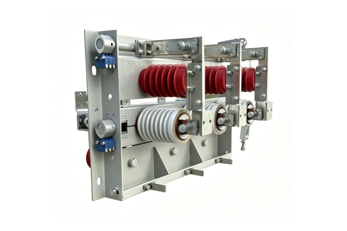
Standard-form GN30-12 assembly shown. The GN30-12D version adds earthing blades. Match the mounting form and operating linkage to the approved order drawing.

Three-pole rotary disconnector for indoor 12 kV, 50 Hz systems. Operate at voltage with the circuit unloaded. Select the paired current and withstand ratings, mounting form, earthing option and operating interfaces to suit the panel.

Rated voltage
12 kV
Maximum voltage
12.5 kV
Rated frequency
50 Hz
Rated-current options
400–1,250 A
4 s thermal withstand
12.5–31.5 kA
Dynamic withstand
31.5–80 kA

Operate only with the circuit unloaded. Thermal and dynamic withstand values are paired by current rating; they are not load-breaking or short-circuit interruption ratings.

GN30-12 technical specifications.

Choose a complete current and withstand combination, then match the mounting form and site conditions. Operate the disconnector only with the circuit unloaded.

Common electrical ratings

Ratings for the GN30-12 and GN30-12D combinations below
No. Item Unit Value
01 Rated voltage kV 12
02 Maximum voltage kV 12.5
03 Rated frequency Hz 50
04 Rated lightning impulse withstand kV 75
05 1 min power-frequency withstand kV 42

Current combinations

Current and withstand combinations
Product form Rated current (A) 4 s thermal withstand (kA) Dynamic withstand (kA)
GN30-12 400 12.5 31.5
GN30-12 630 20 50
GN30-12 1,000 31.5 80
GN30-12 1,250 31.5 80
GN30-12D 400 12.5 31.5
GN30-12D 630 20 50
GN30-12D 1,000 31.5 80
GN30-12D 1,250 31.5 80

GN30-12 is the standard form; GN30-12D specifies an earthing blade. Thermal and dynamic withstand currents are paired with rated current and do not define load-breaking capability. Confirm the full order designation and selected arrangement.

Service conditions

Indoor installation conditions
No. Item Unit Value
01 Altitude m ≤ 1,000
02 Ambient air temperature °C −10 to +40
03 Daily average relative humidity % ≤ 95
04 Monthly average relative humidity % ≤ 90
05 Seismic intensity — ≤ 8
06 Installation atmosphere — No severe dust, chemical corrosion or explosive substances
07 Vibration — No frequent violent vibration

Agree site conditions outside this envelope before ordering.

Mounting and operating options.

Match the upper/lower isolation arrangement, mounting form and operating direction to the panel. Specify earthing and primary contact interfaces together.

Installation arrangements

Arrangement Mechanical and primary fit Operating interfaces and accessories
Seat-mounted assembly Choose upper or lower isolation and match the primary contacts, frame holes and phase spacing to the panel. Specify the operating direction and the standard GN30-12 or earthing-blade GN30-12D form.
Suspension-mounted assembly Use the defined upper/lower reference view when ordering; hanging the assembly reverses its physical top and bottom. Confirm contact orientation, operating access and the linkage on the approved order drawing.
Side-mounted assembly No operating panel. Phases are arranged front-to-back rather than horizontally left-to-right. For a cylindrical shaft, confirm the required hole and slot, mechanism and operating interfaces.

Mounting and primary connections

Upper and lower definition
The nameplate and earthing-contact side is defined as upper. Keep this reference definition when specifying contacts; suspension mounting reverses the physical top and bottom.
Isolation and operating direction
Choose upper or lower isolation, with seat or suspension mounting. Left operation is usual. Right operation requires technical agreement and reverses the upper/lower isolation arrangement.
Phase order
Upright mounting arranges A/B/C horizontally left-to-right. Side mounting arranges the phases front-to-back. Confirm the selected phase order and incoming terminals.
Upper contacts
Choose parallel, vertical or only B-phase vertical contacts. Contacts on the earthing-blade side cannot be vertical.
Lower contacts
Choose parallel, vertical or only B-phase vertical contacts. Apply the same restriction on the earthing-blade side and confirm the complete primary layout.
Phase spacing
Choose 210, 250 or 275; 210 is usual, with a 680 × 300 installation reference. Confirm the dimensions, units and cabinet interfaces on the approved order drawing.
Order identity
State quantity, full GN30-12 or GN30-12D designation, rated voltage and the paired current/withstand combination. Confirm any special requirements with the assembly drawing.


Earthing and operating mechanisms

Earthing and linked operation
Choose no earthing blades, earthing blades, or linked main and earthing blades. Specify GN30-12D for the earthing-blade form and state linked operation explicitly when required.
Incoming-line restriction
The earthing-blade side must not be the incoming-line side. Confirm the designated incoming terminals and the main/earthing operating sequence.
Auxiliary switches
Normally omitted. Specify the main-blade and earthing-blade open/closed contact counts separately. The earthing auxiliary switch is limited to 2K2B.
Voltage-presence sensor
Normally omitted. If required, choose the upper or lower side and confirm its position relative to the incoming terminals.
Operating shaft
A cylindrical shaft requires a mechanism: upright mounting uses a crank, while side mounting requires a shaft hole and slot. An external hexagonal shaft operates with a hand lever without a separate mechanism.
Crank sleeve lengths
For the usual upright arrangement, the main-blade crank sleeve is 100 mm long and the earthing-blade crank sleeve is 178 mm. Confirm the ordered linkage and sleeve fit.
Shaft interface dimensions
Usual cylindrical interface: 90 mm from shaft end to frame hole, Ø30 mm shaft and 430 mm from B-phase centre to shaft end. Usual hexagonal interface: 150 mm end-to-hole and 490 mm B-phase-centre reference. Confirm the exact shaft interface drawing.

GN30-12D with earthing blades

Three views of the earthing-blade assembly. Confirm its final mounting form, incoming terminals and operating linkage against the approved order drawing.

GN30-12D rotary disconnector with earthing blades, earthing-blade view.

Earthing-blade view

GN30-12D rotary disconnector with earthing blades, oblique view.

Oblique view

GN30-12D rotary disconnector with earthing blades, rear view.

Rear view

Outline and installation drawings.

Compare the standard and earthing-blade arrangements. Match the current rating, contact layout and operating direction to the approved order drawing, including dimensions, units, tolerances and cabinet clearances.

Choose an installation drawing

Standard arrangement

Open full-size drawing

GN30-12 standard arrangement installation drawing with original dimensions

Standard installation arrangement. The diagram notes specify 630 A and 20 kA; parenthesized dimensions correspond to the 250 phase-spacing arrangement. Confirm the selected current rating and all dimensions on the approved order drawing.

Open installation drawing page

Earthing-blade arrangement

Open full-size drawing

GN30-12 earthing-blade arrangement installation drawing with original dimensions

Earthing-blade installation arrangement. Confirm the main and earthing blade travel, shaft direction, linkage and cabinet clearances on the approved order drawing.

Open installation drawing page

Manual, selection form and test report.

The manual, selection form and test report cover installation, order options and the tested sample.

Available · PDF · 2 pages

GN30-12 and GN30-12D product manual

Ratings, service conditions, model coding and installation drawings for standard and earthing-blade arrangements. Match the current rating and mounting form to the approved order drawing.

Available · DOC · 2019.04

GN30-12 configuration selection form

Specify upper/lower isolation, mounting, operating direction, earthing, phase spacing, contact layout, auxiliary contacts, sensors and shaft interfaces. Confirm the earthing-side incoming-line restriction and final dimensions.

Available · PDF · 29 pages

GN30-12D/1250-31.5 type-test report

Report 2113345382, dated 6 May 2021, lists six test categories for one GN30-12D/1250-31.5 sample, including power-frequency and impulse insulation, circuit resistance, short-time and peak withstand, 3000-operation mechanical endurance and temperature rise. Match the D arrangement and rated combination; short-time withstand does not establish fault-current interruption.

See Liqiang manufacturing and inspection activities. Model reports and factory inspection records serve different purposes; match the required documents to the proposed equipment.

Price & quotation.

Configuration · GN30-12/630

GN30-12/630 rotary disconnector

Price reference for the specified GN30-12/630 configuration. Standard 630 A rotary disconnector; the D earthing version is quoted separately.

Rated voltage
12 kV
Rated current
630 A
Poles
3

Price range

USD 185–190 / set

USD per complete three-phase set. Minimum order: 1 set. USD 190 per set for 1–19 sets; USD 185 per set for 20+ sets. Shipping and taxes are excluded. Other configurations and accessories require a separate quotation. Confirm the specification and final quotation before ordering.

The range reflects order-quantity tiers for this configuration; it does not cover every option in the series.

Quantity pricing
Published quantity tiers for this configuration
Quantity (sets) Price per set
1–19 USD 190
20+ USD 185

GN30-12 selection questions.

Answers about current ratings, no-load isolation, earthing, installation and ordering requirements.

01Which current and withstand ratings can I specify?

Both GN30-12 and GN30-12D offer these paired current / 4 s thermal / dynamic withstand ratings: 400 A / 12.5 kA / 31.5 kA; 630 A / 20 kA / 50 kA; 1,000 A / 31.5 kA / 80 kA; and 1,250 A / 31.5 kA / 80 kA. Confirm the complete model designation before ordering. See the rating schedule.

02What changes with the GN30-12D earthing arrangement?

GN30-12D adds earthing blades. Specify the earthing position and whether main and earthing blade movement is linked. The earthing-blade side cannot be the incoming-line side; its contact arrangement cannot be vertical. Confirm these interfaces in the configuration choices.

03Can GN30-12 interrupt load current?

GN30-12 is an indoor disconnector for energized, no-load circuit switching. Thermal and dynamic withstand values are not load-breaking or short-circuit interruption ratings. Coordinate isolation with the approved switchgear operating procedure.

04How do mounting and operating direction affect contact positions?

Choose seat, suspension or side mounting. The upper contact reference is the nameplate and earthing-contact side; suspension reverses physical top and bottom. Right operation also reverses the upper/lower arrangement relative to the usual left operation. Side mounting is supplied without a panel. Confirm phase order and both contact directions on the approved order drawing.

05What should I confirm on the installation drawing?

Select the 210, 250 or 275 phase-spacing option and confirm its units, mounting dimensions and tolerances. Parenthesized dimensions in the standard diagram correspond to the 250 spacing arrangement; its technical notes specify 630 A and 20 kA. Confirm the selected current rating, cylindrical or external-hex shaft, lever or mechanism, sleeve and cabinet clearance against the installation drawings.

06What should accompany a GN30-12 quotation request?

Provide quantity, the complete model, rated current, mounting arrangement and operating direction. Include the earthing option, phase spacing, contact layout, shaft interfaces, sensors and auxiliary contacts. Use the manual and selection form with your cabinet drawing to specify the assembly.

Product engineering series

About Liqiang

Manufacturing and technical support.

Technical selection guide