FKN12 vs FZN25: Panel Integration Questions Before Choosing a Load Switch
Durée de lecture : environ 19 minutes
En bref
Compare exact bare-switch or switch-fuse assemblies against one cabinet requirement. Electrical duty, service conditions and physical fit are separate checks.
FKN/FKRN order-defined offsets and FZN cabinet-dependent mechanism thickness are different drawing fields; reconcile the selected handed outline, door and partition interfaces against common datums.
A coordinated fuse combination needs its own envelope, access and striker-mechanism evidence. A fitting fuse or generic family drawing does not establish compatibility or an accepted assembled panel.
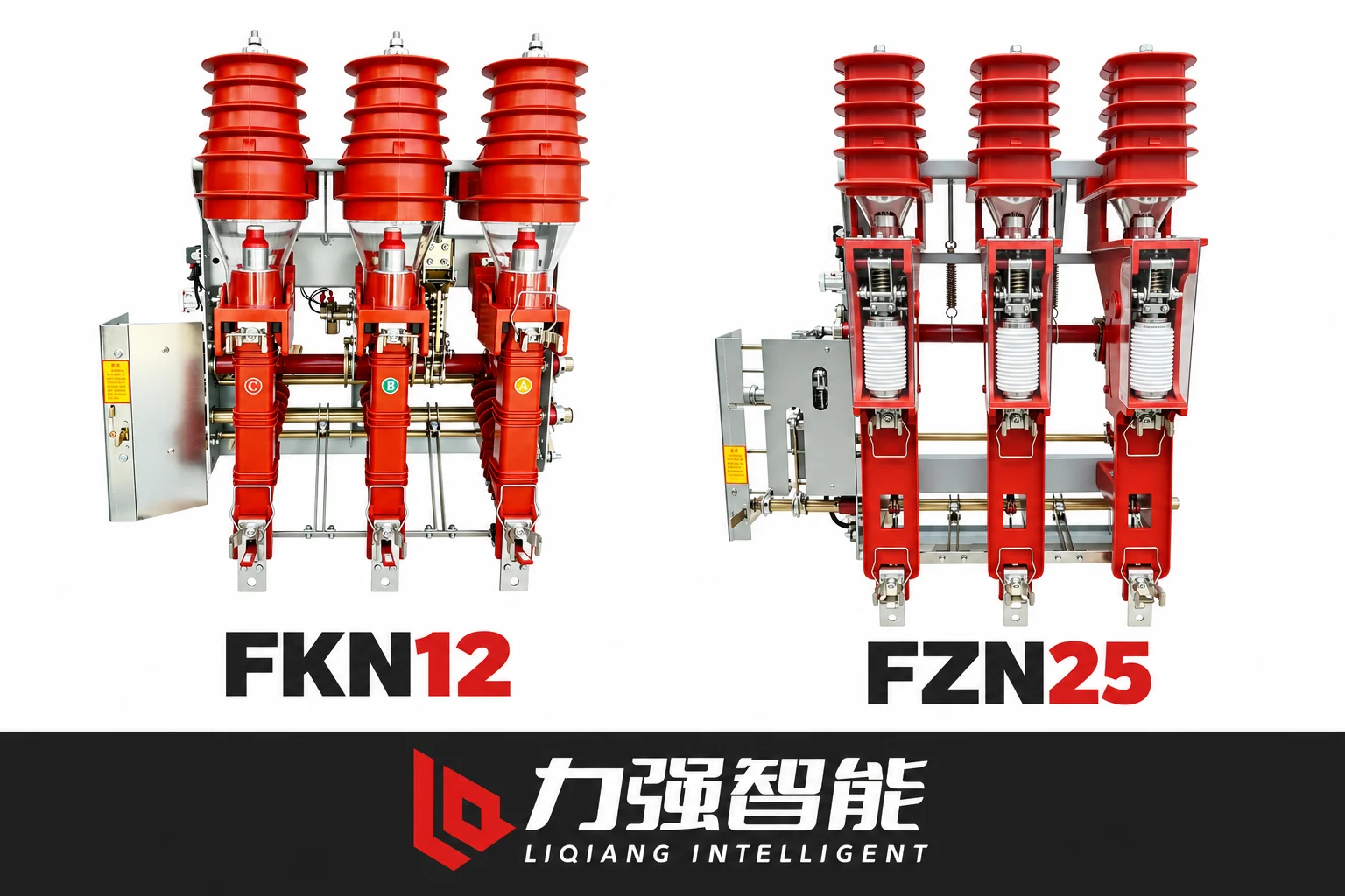
The supplied reference samples show different visible assemblies. They are not presented at a common dimensional scale and do not establish an approved cabinet fit or the complete fuse-combination configuration.
Before a panel builder can meaningfully compare the FKN12 and FZN25 families, one question has to come first: what exactly does the cabinet require, and which specific assembly are you evaluating for each candidate? The comparison only becomes useful when both sides are defined against the same cabinet constraints and both assemblies are identified in full — bare switch or switch-fuse combination, operating side, earthing option and drive type included. Skipping that definition step and comparing a bare-switch outline against a fused installation, or treating visual similarity as a cabinet fit, produces a comparison that cannot be relied on.
The switching duty and interruption principles of these two families are covered separately at What Is a Load Break Switch and are not repeated here. This article focuses on what changes when you place either family into a specific panel: the mounting and mechanism envelope, operating side and handedness, door and earthing interlock geometry, and the additional interfaces introduced when the fuse combination is selected.
Fix One Cabinet Requirement and Identify the Exact Switch Assembly
The right starting point is the cabinet, not the switch catalogue. Before any outline is pulled, the panel integration requirement needs to be fixed: the switchgear duty and network role, the cabinet envelope and internal partition arrangement, the existing operator/front-door position, mounting datums, primary cable or busbar entry directions, and the required service and insulation conditions, and access for operation and fuse replacement where applicable.
Two things are commonly conflated at this stage and should be kept separate. First, the electrical duty qualification — what the switch must do under load and fault conditions — is distinct from the cabinet fit question, which concerns where and how the assembly physically occupies the panel. A switch that satisfies the duty does not automatically fit the cabinet, and physical fit does not establish electrical suitability. A short-time withstand rating does not establish fault-interruption capability; identify which selected component or coordinated assembly performs each required switching and protection duty. Second, a bare FKN12 or FZN25 load switch and its respective FKRN12 or FZRN25 switch-fuse combination are different selected assemblies. The combination adds a fuse holder assembly, a coordinated current path through the fuses, a striker-to-trip mechanical interface and the space and access requirements that come with it. Treating them as the same product at different “configurations” obscures real differences that affect every interface check that follows.
The same logic applies to earthing and drive options. Both product pages list normal/inverted mounting, left/right operating side, earthing switch options and drive type as selectable order fields. These are not universal defaults. The specific combination selected determines the outline, the mechanism position and the interlock geometry. A shared medium-voltage class, similar visual appearance or the same phase spacing does not establish that either candidate matches the cabinet. The interface check only works when the exact selected assembly is identified for each candidate.
Compare the Complete Selected Outlines Against the Same Datums
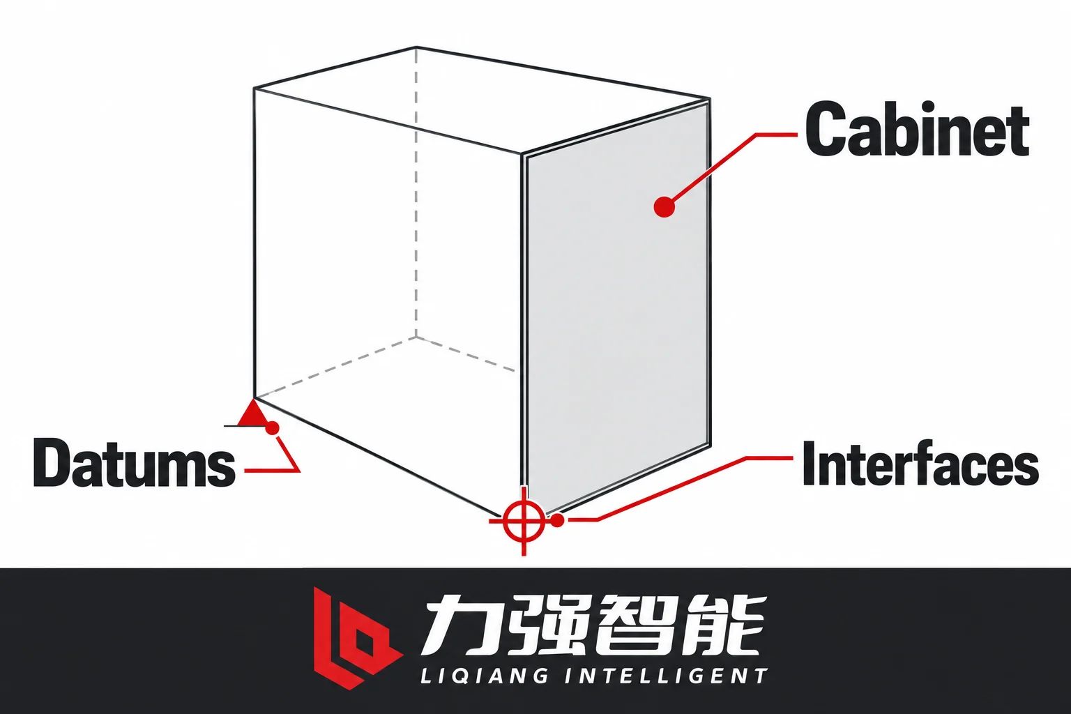
Compare both selected drawing packages against the same cabinet references. This conceptual envelope specifies no dimension, electrical clearance or fabrication detail.
Once the cabinet requirement is fixed and the exact selected assembly for each candidate is identified, both outlines must be compared against the same cabinet datums. An incomplete envelope can mislead the comparison — comparing only the front face of each switch — and missing mechanism, fuse or interlock projections that occupy cabinet depth or side clearance.
The FKN drawing package
The FKN12 installation manual provides separate outline drawings for the ordinary FKN right-operating and left-operating normal installations, and separate drawings again for the FKRN combination right-operating and left-operating normal installations. These drawing identities cannot be merged as a single universal outline. The combination drawings are not simply the bare-switch drawing with a fuse added in front; the combination fuse and fuse-clip assembly runs parallel to the conducting cylinder, occupying a distinct space within the frame.
The mechanism sits to one side of the frame and the notes identify the mechanism offset dimensions L and L1 as user-defined — meaning they are specified at order and must be confirmed from the actual selected configuration drawing, not inferred from a catalogue photo or generic front view. The door-interlock bracket and the FKRN structure legend identify fuse holders, the operating linkage, the earthing switch and the door-interlock bracket/plate interface as separate components, each of which contributes to the complete envelope.
The FZN drawing package
The FZN25 installation manual provides a combined front and side view of the assembly with fuse components, an operating-panel face and labeled earthing and door-lock controls. A note explicitly states that the operating mechanism thickness L is dependent on the cabinet design — it is not a fixed dimension that can be compared across cabinet types. The separate cabinet view locates the assembly relative to the cabinet bottom and front door, showing the interlock pin relationship, and separately drawn door-interlock plate-hole variants illustrate that the hole pattern for the door interlock has configuration alternatives. Middle-partition opening dimensions are shown as a separate figure.
This drawing package is structured around cabinet references in a way that is distinct from the FKN approach. The FZN mechanism thickness depends on the specific cabinet, the interlock holes require the chosen variant and the partition openings apply to the selected configuration. None of these values can be transferred from one cabinet installation to another.
Matching against common datums
When both outlines are placed against the same cabinet datums — the cabinet base, the front-door plane, the mounting rail positions, the primary terminal entry direction — the relevant dimensions to reconcile are: mounting coordinate pattern, primary terminal location and orientation relative to incoming busbar/cable, mechanism envelope on the operating side including any user-defined offset, door-interlock plate and pin relationship, fuse body and access envelope if combination selected, and any required separation to adjacent components or partitions.
Request both complete selected envelopes against the agreed reference planes. Actual configuration drawings must establish the dimensions, separation and access requirements for the cabinet; photographs and generic family outlines cannot supply those values.
Resolve the Operating Side, Drive and Door/Earthing Interface
State the viewing reference when specifying operating side. These blank cards do not imply that a selected mechanism can be reversed in the field.
Operating side directly affects the operator and mechanism interfaces. The label “left-operating” or “right-operating” is meaningful only within the declared viewing reference used in that drawing. If the cabinet drawing uses a different viewing convention, or if someone reads a mirrored drawing without noting the orientation, the comparison can place the mechanism on the wrong side or misalign the operator access path with the front door.
Both product pages list normal/inverted mounting and left/right operation as selectable configuration fields. Do not assume these can be interchanged in the field — they define which drawing applies and which physical arrangement will be delivered. Treating them as reversible after delivery, or assuming a delivered left-operating unit can be made to work as right-operating without a new order configuration, is not supported by the available documentation.
Operating side and mechanism offset together
For FKN and FKRN, the mechanism sits to one side of the frame. The selected mechanism-offset dimensions L/L1 are order-defined. Use the datums shown on the applicable configuration drawing rather than assuming a frame-centre reference. Check the resulting mechanism and shaft position against adjacent busbars, the door-interlock interface and the primary cable or busbar route. A changed offset may alter those clearances and interfaces; reconcile them in the cabinet drawing. The operator interface — whether it is a direct manual handle, a drive linkage or a motor mechanism — must align with the shaft position that results from the selected operating side and offset.
For FZN, the mechanism is described as side-mounted in an integrated frame. The mechanism thickness L is cabinet-dependent and must be selected with reference to the actual cabinet design. The operating-panel face includes labeled earthing and door-lock controls whose positions derive from the selected configuration; these cannot be assumed from a generic drawing.
Drive type and control circuit
Confirm the offered drive for the exact assembly rather than assuming both families have an identical option menu. Where a manual, electric or manual-close/electric-trip arrangement is proposed, identify its operating functions, supply requirements, auxiliary interfaces and model-specific control circuit. Request the actual electrical types, ratings and terminal schedule for that order. Drive selection can change what the panel must provide; it is more than an external handle choice.
For an FKN/FKRN proposal, obtain the approved control and terminal documents for the selected drive from the supplier. The public FKN mechanical references do not supply an FKN12-specific control wiring diagram; an FZN control reference is not a substitute.
Door and earthing interlocks
The FKN manual identifies a door-interlock bracket, plate and panel interface as separate physical components. The FZN manual shows door-interlock pin and plate-hole variants as separate drawings with configuration alternatives. For the selected interlock components, obtain the intended relationship between switch or earthing state and door position. The component drawing alone does not establish every state condition or make every listed interlock a standard feature.
The critical point is that a door fitting over a switch assembly in the available space is not proof that the interlock implements the required safety condition for the project. The interlock geometry — pin position, plate-hole size and location, bracket engagement — must be verified against the chosen components and the project-required state relationship. If the project requires the door to be blocked when the switch is in a particular state, the specific interlock components and their interface to the door must confirm this. Record the required state relationship, the selected components and the applicable drawing revision, then identify the project verification needed before accepting that interface.
Treat a Switch-Fuse Combination as a Different Integration Package
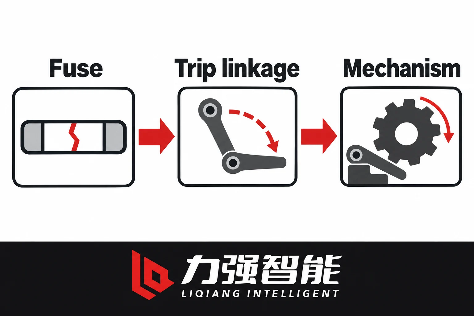
A selected switch-fuse combination includes a compatible striker and trip-mechanism path. The icons show functional roles, not actual part geometry, motion directions or fuse approval.
If the project selects a switch-fuse solution from these families, evaluate the corresponding FKRN12 or FZRN25 assembly for the required duty. A bare FKN or FZN outline with fuse holders added is not evidence of an approved coordinated combination. The selected combination brings additional mechanical, electrical and access interfaces to confirm.
What changes when the fuse assembly is added
In the documented FKRN12 structure, the fuse and fuse-clip assembly lies parallel to the conducting cylinder and differs from the ordinary FKN current path. Its fuse holders, retention and operating linkage belong to the selected combination package. The structure description states that fuse-striker action releases the tripping system. Confirm the offered assembly and its specified action from the combination documents rather than extending that description to every configuration.
The FZRN25 combination description specifically states that fuse-striker action releases its stored-energy switch mechanism for three-phase opening. That is a configuration-specific functional interface, not a promise that any fuse will actuate any switch. Request the selected fuse and mechanism relationship for each offered combination; do not infer identical action or compatibility from the family names.
Why this is not a universal promise
Physical fit and an electrical rating alone do not establish the fuse-striker and trip-linkage match. The selected combination needs compatible retention, striker and mechanism interfaces as well as the required protection coordination. Keep those confirmations tied to the exact offered assembly.
Schneider Electric’s HVL/cc selection guide treats its equipment as an integrated assembly and specifies permitted fuses for that equipment. This illustrates why physical fit alone is insufficient; its fuse list and assembly details do not establish LIQELE compatibility.
For the LIQELE models, the relevant evidence is the configuration-specific documentation for the FKRN or FZRN combination, which defines the fuse assembly scope, the holder and retention interface and the striker-mechanism relationship. Detailed coordination — striker force and stroke, transformer-kVA fuse selection tables, protection calculations — belongs to a later engineering stage and is not addressed here.
Integration consequences
Adding the combination assembly also changes the following interfaces in the panel:
The combination introduces fuse components and interfaces that must be included in its complete envelope. Do not assume a fixed increase in every external dimension or rank the families by size from component count.
Fuse access for replacement requires clearance that must be planned in the panel layout.
The earthing and door-interlock relationships may change, because the combination adds components that the interlock must account for.
The mechanism relationship in the combination is different from the bare switch, because the trip linkage is part of the combination scope.
Requesting a bare-switch drawing and treating it as the envelope for a fused installation will miss all of these additional interfaces. The FKRN or FZRN combination must be specified and its complete assembly drawing must be reconciled against the cabinet.
Two Conditional Panel-Integration Decisions
These two cases are presented as engineering decision paths to illustrate the concrete consequences of the interface gaps identified above. They are conditional examples; the outcome depends on the actual cabinet and selected assembly documents.
Case 1: Retained front-door/operator location and internal partition
Consider a cabinet that has a fixed front-door hinge and opening direction, a defined operator access position, and an internal partition that runs vertically between the switch bay and the busbar section. The panel builder has taken rough measurements of the existing opening and is comparing whether FKN or FZN can be accommodated.
The problem is that the comparison cannot be resolved from rough measurements against a generic outline. The FKN family requires the selected operating side and mechanism offset (L/L1) to place the operating shaft at the correct position relative to the operator access point and the front door. If the mechanism offset conflicts with the partition or places the drive shaft behind a structural member, the proposed configuration remains unresolved even if its front-face outline appears to fit. The FZN family requires the mechanism thickness L, which depends on the cabinet design, and the door-interlock plate-hole variant, which has configuration alternatives. The middle-partition opening dimensions are a separate drawing that must match the partition in the cabinet.
Acceptance in this case requires: the exact FKRN or FKN configuration drawing (with operating side and mechanism offset confirmed), cross-checked against the cabinet front datum, partition position and door-interlock interface. The same is required for the FZN candidate with mechanism thickness and interlock hole variant confirmed. Neither candidate can be accepted on the basis of approximate visual fit. Assign a named cabinet-interface owner, for example the panel integrator working with the switch supplier to obtain both candidates’ configuration drawings for the specific operating side and mechanism position, and reconciling them against the cabinet drawing before proceeding.
What would allow acceptance: the exact configuration drawings for both candidates, reviewed against the confirmed cabinet datum and partition dimensions, with the interlock geometry for each confirmed against the project-required state relationship.
Case 2: Project changes from bare switching duty to switch-fuse combination
Suppose a project initially specified for bare load switching is revised to require a coordinated switch-fuse solution. The panel has been partially sized around a bare FKN or FZN outline.
The consequence is not that the panel builder adds a fuse holder to the existing outline. The FKRN or FZRN proposal needs its own complete assembly drawing, current-path and fuse-access scope, and striker-mechanism interface confirmation. Do not assume either that the bare outline remains valid or that a particular external dimension must increase. The existing cabinet sizing may not accommodate the combination envelope, the fuse access clearance may not exist in the current layout and the door-interlock interface may differ.
The evidence needed: the FKRN or FZRN combination outline drawing for the selected configuration, including fuse holder positions, fuse access envelope, striker-mechanism interface scope and any changed earthing/door-interlock geometry. This must be compared against the current cabinet layout drawing. Assign a named scope owner, such as the project engineer, to confirm the revised assembly selection, request the combination configuration drawings from the supplier and re-evaluate the cabinet layout against the new envelopes before committing to cabinet steel.
What would allow acceptance: a confirmed combination drawing for the selected FKRN or FZRN configuration, cabinet layout re-evaluated against the combination envelope, fuse access confirmed in the available cabinet space, and the interlock interface confirmed for the combination.
Issue a Two-Candidate Drawing Request and Close the Interface Gaps
Reconcile the selected switch and cabinet drawings, and assign each unresolved interface. The blank records show no approved geometry or accepted fit.
The following table structures the drawing request and evidence record for comparing an FKN/FKRN candidate against an FZN/FZRN candidate for the same cabinet. Each row identifies the interface, the exact drawing or field required from each candidate, what evidence is needed and who owns the open action. The purpose is to make every gap visible before a choice is made, not to produce an approved fit or a ranked result.
Interface
Common Cabinet Requirement
FKN/FKRN Candidate — Drawing/Field
FZN/FZRN Candidate — Drawing/Field
Evidence/Revision Required
Owner / Open Action
Assembly identification
Bare switch or combination; earthing option
FKN12 or FKRN12, earthing configuration, product code
FZN25 or FZRN25, earthing configuration, product code
Supplier-confirmed order code and governing configuration revision
Panel builder confirms exact product code for each candidate
Duty / service basis
Required switching/protection duty, service and insulation conditions
FKN (load switch only) or FKRN (switch-fuse combination) scope confirmed
FZN (load switch only) or FZRN (switch-fuse combination) scope confirmed
Project duty definition; combination requires coordinated fuse scope — not evaluated in this stage
Project engineer confirms duty and combination scope requirement
Mounting / view / orientation
Cabinet base reference, front-door plane, mounting rail pattern
Normal or inverted; operating side (left/right) per selected configuration drawing
Normal or inverted; operating side (left/right) per selected configuration drawing
Selected configuration outline drawing for each; viewing reference declared
Both candidates: obtain configuration-specific drawings
Mechanism offset/thickness
Available side clearance on operator side, partition clearance
User-defined L/L1 offsets from configuration drawing
Cabinet-dependent mechanism thickness L from configuration drawing
Configuration drawing with confirmed offset/thickness for this cabinet
Supplier provides value for selected order; panel builder reconciles against cabinet
Order drawings reconciled with the cabinet; required duty/combination evidence and assembled-panel verification status identified
Panel builder marks each row resolved before proceeding to panel manufacture
What this table does and does not establish
A completed table with drawings reconciled against the cabinet means the document interfaces are resolved on paper. It does not mean the assembled panel has been built and verified. The distinction matters: drawing reconciliation is a necessary condition for proceeding, not a substitute for the physical build and acceptance test that the project specification requires. Keep each unresolved requirement assigned to a named project owner, with the evidence and close condition needed before the decision that depends on it. Rows cannot be closed with approximate values or photographs.
Conditional choice criteria
A candidate needs the required electrical duty and service conditions confirmed, with its applicable cabinet interfaces resolved. A configuration that meets those requirements without changes to retained cabinet constraints may be preferable to one that needs an agreed cabinet revision. A larger count of completed document rows is not a substitute for resolving a critical duty, interlock or access gap. If both proposals meet the requirements, the project can then weigh the remaining commercial and standardisation inputs.
Next steps and enquiries
To obtain the configuration-specific drawings for either family, start with the product pages:
To submit your specific cabinet requirement and request both candidate configuration drawings directly, use the page de contact.
Foire aux questions
Can I use the same drawing for both left-operating and right-operating configurations?
Use the drawing approved for the selected operating side and assembly. The FKN documentation gives separate left- and right-operating normal-installation drawings for ordinary FKN and FKRN combination arrangements. A mirrored image is not an approved substitute for the correct order drawing. For either family, confirm the viewing reference, mechanism position and door/interlock interfaces against the actual cabinet rather than inferring them from the opposite-hand illustration.
Why is the mechanism thickness a concern for FZN but not described the same way for FKN?
The FZN installation example makes mechanism thickness L dependent on cabinet design. The FKN/FKRN drawings identify order-defined offset dimensions L/L1. These labels describe different drawing fields; the shared letter L does not make the quantities interchangeable. Obtain their values, datums and applicable configuration revision for the proposed order, then reconcile the complete mechanism envelope against the same cabinet references.
Does selecting an FKRN or FZRN combination mean any medium-voltage fuse of the right current rating will trigger the switch?
No. Current rating and physical fit do not establish compatibility with the selected holder, striker or trip mechanism, or complete the required protection coordination. The documented FKRN structure identifies a striker-to-trip interface; the cited FZRN description specifically states three-phase opening through its stored-energy mechanism. Confirm the offered action and permitted fuse specification for each exact combination. Do not transfer one model’s functional description or fuse choice to the other.
Partagez votre amour
William Xiaonan Liu
William Xiaonan Liu rédige pour LIQELE des articles consacrés aux équipements de commutation moyenne tension, notamment les disjoncteurs à vide, les interrupteurs de charge, les sectionneurs et les commutateurs de mise à la terre. Ses articles traitent du choix des produits, des interfaces d'installation, des exigences de fonctionnement et de la documentation technique, aidant ainsi les fabricants d'appareillages de commutation et les acheteurs de projets à identifier les informations nécessaires à la sélection des équipements et aux discussions avec les fournisseurs.
Disjoncteurs à vide pour usage intérieurInstallation des panneauxComparez les structures et les interfaces des armoires.Fixe / amovibleAppareillage de commutation pour usage intérieurDisposition au solDisposition à trois positionsDisposition centraleDisjoncteurs à vide pour usage extérieurLignes de distributionPasser en revue les dispositifs d'alimentation, de détection et de commande.Commutation d'alimentation / de limiteDistribution en extérieurInterrupteurs de coupure en chargeCommutation et intégration dans les armoires électriquesComparez les modes de commutation et les configurations des armoires.Interrupteur de charge à jet d'airInterrupteur de charge sous videDisposition des pôles intégrésSectionneurs et interrupteurs de mise à la terreIsolation et mise à la terreVérifier l'isolation, la mise à la terre et les interfaces de fonctionnement.Sectionneur d'intérieurSectionneur rotatif d'intérieurInterrupteur de mise à la terre pour usage intérieurDisjoncteur à vide débrochable VS1-12 à pôles intégrésEnsemble disjoncteur à vide pour usage extérieur ZW32-12 avec sectionneurEnsemble d’interrupteur de coupure en charge sous vide pour usage intérieur FZN25Ensemble de sectionneur rotatif d'intérieur GN30-12Disjoncteur à vide d'intérieur VS1-24Configuration type d'un disjoncteur d'intérieur ZN85-40.5Vue de face d'un disjoncteur à vide d'intérieur VQL-12 à trois positionsDisjoncteur à vide VQL-24GD/630-25Configuration type d'un disjoncteur à trois positions VQLA-12 à montage centralConfiguration type d'un disjoncteur à vide pour usage extérieur ZW20Configuration type d’un interrupteur de coupure en charge FKN12Interrupteur de coupure en charge sous vide FZN64-12GDInterrupteur de coupure de charge à pôle intégré VZF, vue arrièreSectionneur d'intérieur GN19-12, vue de faceSectionneur d'intérieur GN27-40.5, vue de faceConfiguration type du commutateur de mise à la terre intérieur JN15Gamme de produitsConfiguration typeCoup de projecteur sur un produitVoir tous les produitsDiscutez de vos besoinsRépertoire des sériesAfficher la catégorieCatégories de produitsConfiguration type d'un produitAfficher/masquer la gamme de produitsNavigation principale LIQDemander un devisDemander un devis