Remote-Controlled Outdoor Breakers: Write the I/O List Before Choosing a Protocol
Durée de lecture : environ 18 minutes
En bref
Define each I/O point by its function, origin and direction across a named boundary. A protocol name, motor or local indicator does not establish the supplied remote interface.
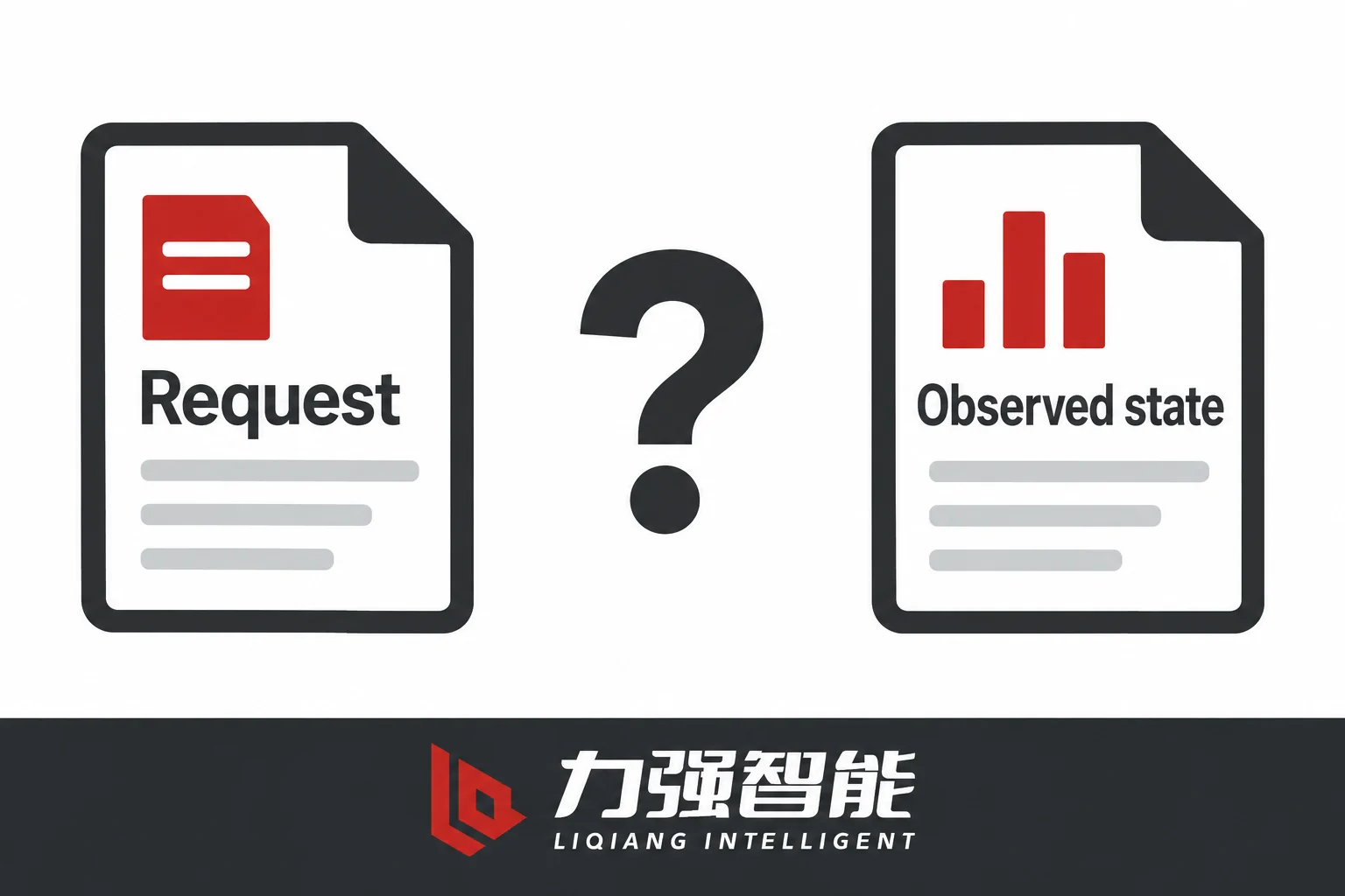
Keep request receipt, command disposition, actuator output and documented device-state feedback separate; Accepted alone proves neither forwarding nor contact movement.
Trace each required point through the circuit, controller, any gateway and supervisory display, with electrical or logical definitions, quality, timing, revisions and an owner for every open interface.
An illustrative automation workspace frames command and feedback as different information roles. It shows no actual site, installed interface or validated control result.
A protocol name alone does not define who may issue a command, what a Closed indication represents, or who owns the signal path from the device to the supervisory display. Write the required I/O functions and their meaning before confirming protocol compatibility. That gives the equipment supplier and integrator a common record against which to check the selected controller, circuit and mapping.
The I/O list should distinguish commands from state observations, define quality and timing, and trace each point through the integration layers. The following fields and two project cases show what to confirm before an interface is treated as matched.
Define Remote Functions and Signal Direction Before Choosing a Protocol
The starting point is not a device datasheet. It is the operator or automation task: what does the supervisory system need to do, and what does it need to know?
From that task you can define the information classes that the I/O list will carry. They are not interchangeable:
Command request — an instruction from the supervisory system or controller toward the device. Direction: downward from the supervisory boundary. Examples: close request, open request.
Condition or permissive — a state that must be satisfied before a command can be executed. Direction: determined by the scheme logic. A permissive is not itself a command. Define separately how the approved scheme handles any existing request when the condition changes.
Device-state indication: feedback from a defined device contact, switch or logic source. State what physical condition that source represents and how its validity is established. For a selected reporting path, direction is from that source toward the supervisory system. An indication is different from a last command and is evidence only for the state and scope documented for its source.
Event or alarm: distinguish a recorded occurrence, such as a trip event, from an active or latched alarm condition. Specify the source, meaning, timestamp and any relevant reset semantics. For a selected reporting path, direction is toward the supervisory system. Neither a trip event nor an alarm is a substitute for current position feedback.
Measured value — a continuous or sampled quantity such as current or voltage, originating at a sensing interface. Direction: upward.
Stating direction relative to a named boundary matters. “Input” and “output” are ambiguous without a reference: a close command is an output from the controller and an input to the actuator circuit. The I/O list must name the boundary — primary device, controller, gateway, supervisory system — and state direction relative to that boundary for every point.
A motor inside the mechanism is not a remote I/O point. A local open/closed indicator on the panel is not a remote I/O point. A selectable intelligent controller connected by a sealed cable is not by itself evidence that a remote I/O list has been supplied or agreed. The ZW20 series, for example, describes a separate controller and connector interface with optional and selected remote functions; the working-principle passages establish that a charging motor, a limit switch, and local close/open indication are present, but they do not constitute a delivered remote point list. Similarly, the ZW32-12 electrical secondary wiring figure identifies a QF auxiliary switch, spring-energy travel switches, separate closing and opening coils and a charging motor — distinct functional elements, not a pre-agreed remote export. What remote functions are required and what authority they carry are project inputs, agreed between the enquiring engineer and the equipment supplier, not default family-wide features.
Separate Commands, Acceptance, Permissions and Confirmed Movement
A request record is not confirmation of actual contact state. Define the feedback source, validity and required response interval separately.
Once the required commands are identified, define the four observations that may be available along the selected command path. Their availability and meaning depend on the controller and integration scheme.
Send or request — the supervisory system or HMI issues a command. This is a record of intent. It proves nothing about what happened downstream.
Controller accepted, rejected or inhibited: the receiving layer records a disposition, if supported. Define what Accepted means at that layer: receipt, validation, selection or another documented stage. It must not be assumed to mean the command was forwarded or that an actuator was energised. Record rejection or inhibition reasons where available, separately from the HMI send record and actual device-state feedback.
Actuator command: an output toward the selected mechanism, if that observation is available. In the documented spring-operated examples, closing and opening coils are distinct from position-related auxiliary contacts. The ZW20 description also separates the command signal from the subsequent electromagnet and latch response. Do not transfer that mechanism arrangement to every offered drive, or infer completed movement from an output command.
Device-state feedback: an indication with a documented physical or logical origin, state reference, timing and quality. Confirm how an auxiliary-switch or mechanism indication relates to the main contacts in the selected equipment. A fresh display timestamp alone does not prove a fresh device observation, movement of every pole or electrical isolation.
Keep these observations distinct in the I/O list and identify which are actually available. The command-authority field records who may issue a request and under which local/remote selection state. Specify how each remote request is handled when authority is unavailable or changes. Do not infer autonomous protection behaviour from a selector label; its relationship to remote commands and protection functions needs the approved scheme.
Define the applicable permissives and readiness conditions from the approved scheme. A permission is not itself stored-energy readiness or a safety clearance. For an unmet condition, record the supported request disposition, expiry or cancellation rule and whether a new authorised request is required. Do not assume that an earlier request will execute automatically when a condition later clears.
Command duration and type also need definition: is the close command a maintained signal or a pulse, and for how long? The I/O list records the required type as a field; it does not fill in specific timing values without the selected controller documentation.
Assess a command/state discrepancy using the disposition at each relevant layer, valid feedback and the approved response interval. The expiry of that interval does not by itself prove a mechanical failure. Record the evidence and responsible interface owner needed to resolve the discrepancy under the project procedure; a trial operation is not a substitute for a defined signal path.
Give Position, Readiness and Alarms Their Own Meaning and Quality
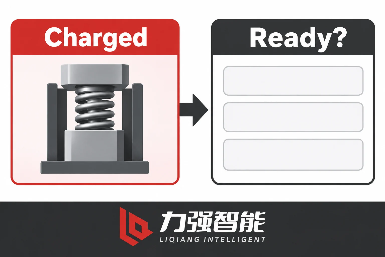
For a selected spring arrangement, charged is one mechanism condition. A composite readiness definition needs its own specified conditions and evidence; this illustration establishes no exported point or implemented logic.
Three common mistakes in I/O lists for outdoor breakers involve position, readiness and alarms being given the wrong meaning or being treated as interchangeable.
Position is not a last command
The open/closed indication must refer to an actual contact or auxiliary switch state at the device, originating in the device circuit, not to the last command sent. These diverge when a command fails to execute, when an autonomous trip occurs, or when a communication interruption leaves the supervisory display frozen on a previous value. The I/O list must record: what physical contact or auxiliary switch state is the source, what is the reference state (what physical condition corresponds to the logical “closed” value), and what is the channel origin — a hardwired DI, a communication object, or a calculated logical point in the controller.
For the ZW32-12, the secondary wiring figure shows a QF auxiliary switch with position-related contacts as a separate element from the spring-energy travel switches. These are not interchangeable; do not assume auxiliary-contact meanings or dual-point encoding without the actual state reference and approved export/controller mapping.
Spring charged is not composite readiness
The ZW20 working-principle passages describe a limit switch that removes motor power when spring charging is complete. The ZW32-12 wiring figure separately identifies spring-energy travel switches. These are distinct mechanism-internal functions. Their contact states and relationship to a reported Charged point need the applicable drawing and state reference. A “charged” or “spring OK” point, if exported, tells you that one specific mechanism condition is present. It does not tell you that all other conditions required for a successful close are also present.
A composite Ready to Close point needs a definition for the selected drive and approved scheme. Candidate conditions may include energy readiness, control supply, authority and applicable interlocks, but the required logic is configuration-specific. If this point is requested, identify its source logic and validity separately from a Charged indication.
Local display of spring charge status or an internal motor cutoff switch does not constitute an exported controller point. Whether a charged indication is available as a remote output depends on the ordered configuration and the approved circuit documentation.
Alarms are candidate requirements, not universal defaults
Supply supervision, controller supervision, trip cause, failed-command alarm and communications loss alarm are all candidates that may appear in a remote I/O list. Whether any of them is actually implemented depends on the selected controller, the ordered configuration and the approved scheme. The I/O list should list them as candidates with a status field — required, to be confirmed, or not applicable — not as default inclusions.
Quality, timestamp and freshness
For each applicable point, define the following quality and timing fields; command records also need their own request and disposition timestamps:
Timestamp and source — when was the value last updated, and at which layer (device event, controller scan, gateway poll, HMI refresh)?
Validity and staleness — what age of value is acceptable, and how does the supervisory system indicate that a value is stale?
Discrepancy handling — if two sources disagree about the same physical state (for example, a hardwired DI and a communications object that should both reflect contact position), what is the defined response?
A healthy communications link is not proof that the physical state it is reporting is correct. A lost communications link does not establish that the contacts have changed state. The last-known value displayed on the supervisory screen after a link interruption is a historical record with a timestamp, not a current observation.
Allocate Each Point from the Primary Interface to the Supervisory Display
Trace command and feedback meaning through the project’s responsibility layers. These are functional roles, not an actual hardware or wiring topology.
The I/O list is only useful if every point has an identified owner at each layer of the integration. A responsibility matrix across four named layers — device/circuit, controller physical I/O or internal logic, any RTU or gateway, and HMI/SCADA — makes the ownership explicit.
The following is an allocation template. Assign an actual owner for each boundary in the project; the example roles do not establish a universal supplier/buyer split:
Layer
Owner responsibility
Required evidence
Device / circuit
Device manufacturer confirms which contacts or switches are available, their reference state, and electrical character
Approved circuit drawing with component legend
Controller physical I/O or internal logic
Assigned controller owner documents the applicable input/output electrical type and rating, internal logic source and point mapping
Controller I/O handbook and project point map
RTU / gateway (if present)
Integration contractor maps controller objects to the communications protocol representation, including data type, scaling and direction
Gateway configuration record with revision
HMI / SCADA
System integrator maps the received object to a display point with defined label, state representation and staleness indicator
HMI tag database with point-map revision
Assigning a named owner per layer is not the same as a generic “manufacturer supplies hardware, buyer configures software” split. The circuit drawing and the controller point map serve different purposes and must both trace the same intended function from source to display.
For hardwired points, identify the actual source and receiver: for example a voltage-free contact or an energised signal, where applicable. Compare the source/output and receiving-input types, ratings, state reference and relevant polarity or loading conditions from their documents. A mating connector and a cable of sufficient reach do not establish electrical compatibility. Keep these interface fields distinct from a logical point name.
For logical or communications points, the required fields are: direction relative to the named boundary; meaning (what physical state or event does this object represent); data type (Boolean, integer, enumerated, timestamp); state or value representation; validity and timestamp origin; and mapping revision.
Schneider Electric’s IOEX module documentation specifies controller-dependent input/output types, ratings and compatibility. That example shows why a point name or matching cable is insufficient. It does not establish the electrical interface, accessory compatibility or supplied points of a LIQELE configuration.
Resolve Two End-to-End Signal Misunderstandings
Two scenarios come up repeatedly in outdoor breaker integrations. Neither has a simple universal answer, and both require the I/O list to have been written correctly before they can be resolved.
Case 1: Close request accepted, no valid closed indication within the response interval
What happens: The HMI records a close request. The controller returns an accepted disposition. The approved response interval passes. No valid closed indication appears on the supervisory display.
What the I/O list must answer before you can investigate:
The command route: did the close request reach the controller, and is the accepted disposition recorded in the controller event log? The controller’s own log is a separate record from the HMI send record; both must be checked.
The authority and permissive state at the time: was the remote/local selector in the correct position? What disposition and any supported output-stage record were available under the applicable authority and permissive conditions? If a rejected disposition appears as Accepted at the HMI, check the disposition semantics and the controller-to-display mapping. That inconsistency does not establish a mechanical failure.
The actual feedback path: is the closed indication sourced from a hardwired DI, a communications object, or both? Is the controller correctly mapping the device auxiliary contact to the expected communications object? Has the controller point map been verified against the approved circuit drawing?
What not to do: Do not assume the mechanism failed mechanically. Do not operate the equipment locally to find out. The relevant evidence includes available controller and source-state records with their timing and quality, and the approved point mapping — not a trial operation. Assign owners for the command and feedback interfaces. Reconcile those paths against the approved configuration and available functional evidence; where evidence is missing, identify what the project verification plan must establish.
Case 2: Link interruption leaves a last-known closed indication on the supervisory display
What happens: A communications link between the gateway and the HMI is interrupted. The HMI continues to display a closed indication. The link is later restored.
What the I/O list must answer:
What is the timestamp of the last received value? Is the staleness clearly shown on the supervisory display — for example, a greyed-out symbol, a time-since-update counter, or a quality flag? What is the defined refresh interval, and at what age does the value transition from current to stale?
Is the closed indication sourced from a hardwired DI at the controller as well as from the communications path? If a hardwired path exists independently of the communications link, does the HMI have access to it, or is all display information routed through the interrupted link?
What not to assume: The contacts may have opened during the link interruption, or they may still be closed. A last-known value with a stale quality flag is historical information, not a current verified state. Do not interpret a stale closed indication as proof that the contacts are still closed, and do not interpret the link interruption as evidence that the contacts opened. The defined behaviour — what the HMI displays, what quality flag is shown, and what action the operator is expected to take — must be in the I/O list as a specified requirement before integration begins.
For each case, assign the affected interface owners and identify the available event/source-state records, governing circuit and point-map revisions, communications configuration and project verification requirements. A plan states what should be checked; completed records with the required source, timing and quality provide the evidence for closing the action.
Hand an I/O Schedule to Protocol and Integration Confirmation
Reconcile each point’s defined meaning with its actual mapping, and assign unresolved fields. The blank record contains no address, protocol or accepted result.
Once the point definitions are complete, the I/O list can be presented in a form that supports protocol selection and integration verification. The candidate point list below represents the rows that need explicit confirmation as requirements; they are not a supplied default set.
Candidate point list — outdoor breaker remote I/O
Point
Class
Direction
Origin
Meaning / State reference
Candidate type
Statut
Close request
Command
↓ Supervisory → Device
HMI / Controller
Request to close primary contacts
To confirm
Requirement to confirm
Open request
Command
↓ Supervisory → Device
HMI / Controller
Request to open primary contacts
To confirm
Requirement to confirm
Command disposition
Acknowledgement
Controller to supervisory system
Named receiving layer
Documented receipt, acceptance, rejection or inhibition stage and reason
To confirm
Requirement to confirm
Closed indication
State feedback
Defined device source to supervisory system
Selected auxiliary contact or other documented source
State and relation to main contacts defined by the approved drawing
To confirm
Requirement to confirm
Open indication
State feedback
Defined device source to supervisory system
Selected auxiliary contact or other documented source
State and relation to main contacts defined by the approved drawing
To confirm
Requirement to confirm
Spring charged
Mechanism state
↑ Device → Supervisory
Mechanism travel switch
Closing spring charged; not composite readiness
Conditional
Requirement to confirm if exported
Selected permissive
État
Defined source to receiving logic and, if required, supervisory system
Approved scheme logic
Meaning, validity and effect on the relevant request
Conditional
Requirement to confirm if applicable
Selected measured value
Mesure
Selected sensing/controller source to supervisory system
Specified measurement channel
Quantity, units, reference, scaling and quality
Conditional
Requirement to confirm if required
Ready to close
Composite readiness
↑ Device → Supervisory
Controller logic
Defined combination of conditions; logic to be specified
Conditional
Requirement to confirm if applicable
Remote / Local
Authority state
↑ Device → Supervisory
Selector switch or controller
Current command authority mode
To confirm
Requirement to confirm
Trip event
Event
↑ Device → Supervisory
Controller / Protection
Discrete trip occurrence with timestamp and cause code
Conditional
Requirement to confirm
Supply / Controller supervision
Alarm
↑ Device → Supervisory
Controller self-monitoring
Control power or controller health; not universal default
Conditional
Requirement to confirm if implemented
Communications supervision
Alarm
↑ Device → Supervisory
Gateway / Controller
Link health or poll failure
Conditional
Requirement to confirm if implemented
Point definition fields for each confirmed row:
For each row, complete the applicable fields below and explicitly mark any field that is not applicable to its point class:
Point identity and class
Boundary and direction (relative to named layer)
Physical or logical origin (named component and drawing reference)
Meaning, state reference or units
Physical type or contact rating (for hardwired points)
Data type and state representation (for communications objects)
Controller map reference and revision
Acknowledgement or disposition semantics
Timing, response interval and quality/timestamp expectation
Owner at each layer
Supporting evidence reference
Open action or confirmation status
Only after this record is populated does a protocol selection conversation become productive. Specifying a protocol name or confirming that a cable physically connects does not constitute interoperability confirmation. The required information is: which protocol version and profile, which object model or data class, which command semantics (select-before-operate versus direct operate, if applicable), what transport and session parameters, and how the gateway maps controller objects to the protocol representation and vice versa.
Documented mapping is not the same as verified end-to-end behaviour. The I/O schedule records the agreed definitions and mapping. A project verification plan defines the checks for the actual configuration; completed records from those approved checks establish the demonstrated end-to-end behaviour. Assign the relevant owners and completion criteria explicitly rather than treating an agreed schedule or an unexecuted plan as a test result.
For related scope on system-level selection, see outdoor circuit breaker versus recloser. For current-sensing interface specification that feeds measured-value points, see CT selection. For voltage and operating-supply duties that affect control power and measured-value availability, see PT and voltage sensor.
Next Steps
If you are preparing a remote I/O enquiry for an outdoor breaker application, the right starting point is the operator task and system boundary — not a protocol shortlist. Work through the information classes, define direction relative to named layers, confirm which points are required versus conditional, assign owners per layer, and document the open actions before any wiring or configuration begins.
Does a controller accepting a close command confirm that the contacts moved?
No. Accepted has the meaning defined by the receiving layer and controller; it may record receipt or another processing stage without proving forwarding or actuator energisation. Assess subsequent feedback against its documented source, state reference, timing and quality. An auxiliary indication is evidence for its specified relationship to the mechanism or main contacts, not automatic proof of every pole or isolation. If valid expected feedback does not follow within the approved interval, reconcile the command and feedback paths using available records rather than assuming mechanical failure.
What does a Spring Charged point establish, and why is it not the same as Ready to Close?
For a spring-operated mechanism, a documented Charged point reports the defined spring-energy condition. An internal cutoff or travel switch does not by itself establish an exported point or its state mapping. Ready to Close is a separate, configuration-specific assessment of the conditions required by the selected drive and scheme. Specify its logic, source and validity if requested. A Charged indication alone does not establish all applicable authority, supply or interlock conditions, and it does not prove that a close operation will succeed.
If the communications link is lost and the supervisory display still shows Closed, what does that mean?
The Closed symbol alone is insufficient to tell. If its data source was the interrupted path, the display may retain a last-known value or apply another configured loss-of-quality behaviour. A separate valid source may also exist. Check the documented source, acquisition time, freshness and quality rules. A retained value does not establish current contact state; loss of the link does not establish contact movement. Define how stale or unknown information is shown and how it relates to the approved project response procedure, without assuming a universal fail state.
Partagez votre amour
William Xiaonan Liu
William Xiaonan Liu rédige pour LIQELE des articles consacrés aux équipements de commutation moyenne tension, notamment les disjoncteurs à vide, les interrupteurs de charge, les sectionneurs et les commutateurs de mise à la terre. Ses articles traitent du choix des produits, des interfaces d'installation, des exigences de fonctionnement et de la documentation technique, aidant ainsi les fabricants d'appareillages de commutation et les acheteurs de projets à identifier les informations nécessaires à la sélection des équipements et aux discussions avec les fournisseurs.
Disjoncteurs à vide pour usage intérieurInstallation des panneauxComparez les structures et les interfaces des armoires.Fixe / amovibleAppareillage de commutation pour usage intérieurDisposition au solDisposition à trois positionsDisposition centraleDisjoncteurs à vide pour usage extérieurLignes de distributionPasser en revue les dispositifs d'alimentation, de détection et de commande.Commutation d'alimentation / de limiteDistribution en extérieurInterrupteurs de coupure en chargeCommutation et intégration dans les armoires électriquesComparez les modes de commutation et les configurations des armoires.Interrupteur de charge à jet d'airInterrupteur de charge sous videDisposition des pôles intégrésSectionneurs et interrupteurs de mise à la terreIsolation et mise à la terreVérifier l'isolation, la mise à la terre et les interfaces de fonctionnement.Sectionneur d'intérieurSectionneur rotatif d'intérieurInterrupteur de mise à la terre pour usage intérieurDisjoncteur à vide débrochable VS1-12 à pôles intégrésEnsemble disjoncteur à vide pour usage extérieur ZW32-12 avec sectionneurEnsemble d’interrupteur de coupure en charge sous vide pour usage intérieur FZN25Ensemble de sectionneur rotatif d'intérieur GN30-12Disjoncteur à vide d'intérieur VS1-24Configuration type d'un disjoncteur d'intérieur ZN85-40.5Vue de face d'un disjoncteur à vide d'intérieur VQL-12 à trois positionsDisjoncteur à vide VQL-24GD/630-25Configuration type d'un disjoncteur à trois positions VQLA-12 à montage centralConfiguration type d'un disjoncteur à vide pour usage extérieur ZW20Configuration type d’un interrupteur de coupure en charge FKN12Interrupteur de coupure en charge sous vide FZN64-12GDInterrupteur de coupure de charge à pôle intégré VZF, vue arrièreSectionneur d'intérieur GN19-12, vue de faceSectionneur d'intérieur GN27-40.5, vue de faceConfiguration type du commutateur de mise à la terre intérieur JN15Gamme de produitsConfiguration typeCoup de projecteur sur un produitVoir tous les produitsDiscutez de vos besoinsRépertoire des sériesAfficher la catégorieCatégories de produitsConfiguration type d'un produitAfficher/masquer la gamme de produitsNavigation principale LIQDemander un devisDemander un devis