What Is an Earthing Switch? Function, Making Duty and Withstand Ratings
Approx. 14 min read
Quick Takeaway
An earthing switch closes a defined connection between a selected circuit section and the installation earthing system. Current interruption and supply isolation remain separate functions; one earthing point does not automatically earth every part of a cabinet.
Contacts, blades and conducting connections establish the earth path, while supports, shaft and stored-energy mechanism provide location and motion. A closing spring delivers mechanical energy; its presence alone does not establish short-circuit making capability.
Short-circuit making concerns establishing current during closing. Short-time withstand specifies current together with duration, while peak withstand addresses the highest instantaneous stress. These are distinct assigned duties of the selected version, rather than interchangeable ratings.
An earthing switch is a switching device whose closing contact arrangement connects a defined circuit section to the earthing path of the installation. Its contacts and conducting connections establish the intended path from that section to earth. In a switchgear bay, this function belongs alongside current interruption and supply isolation.
Three duties that get collapsed into one word have to be kept apart from the start. Interruption ends a current that is already flowing. Isolation establishes the assigned separation at a section’s supply boundary. Earthing adds a defined, deliberate connection to earth. These are performed by different devices, or by different parts of a combined device, and each has its own rating basis. An earthing switch is the third. Its presence tells you nothing about breaking capability, and a device does not inherit a load-switch or breaker function merely because a bay contains one.
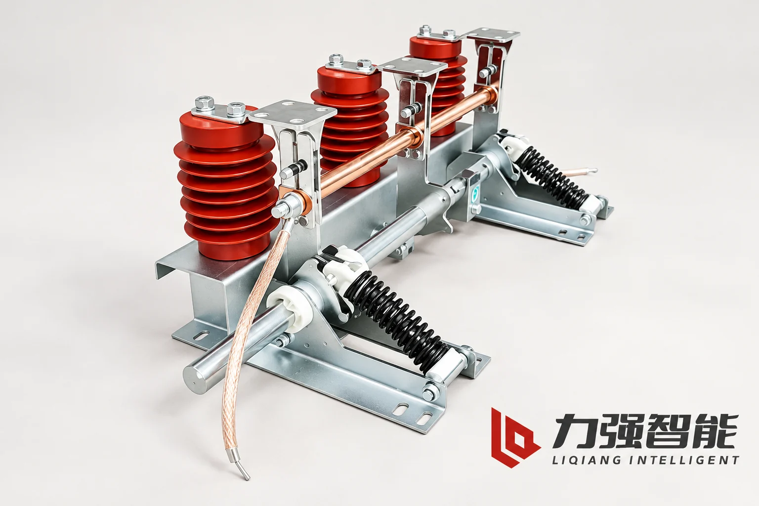
The JN15 assembly brings together switching contacts, conducting connections, insulating supports and the operating mechanism on a common frame.
What the earthing function connects, and why
The earthing switch works on a circuit section that is intended to be de-energized — a cable run, a busbar section, a transformer winding, whichever portion the device is actually connected to. Closing it provides the intended connection between that portion and the installation earthing system. The connection offers a defined conducting path for charge and induced current rather than leaving the section electrically floating. If the section becomes energized, fault current may also flow through the earth connection; its assigned duties and the circuit protection then matter.
ABB’s Distribution Automation Handbook describes earthing equipment in these terms — as a device that earths and short-circuits a defined portion of the installation, either as an independent unit or combined with an adjacent disconnecting or switching device. The same source draws the distinction that matters most for reading ratings: the circuit duty of an earthing arrangement is not the duty of the continuous load-current-carrying main circuit. A device may be assigned a defined fault withstand, and some stored-energy closing devices may additionally carry a specified fault-making capability. Neither statement is a statement about carrying normal load current.
Liqiang’s JN15 indoor earthing-switch manual follows the same structure for a specific construction. Its overview places the device in switchgear assemblies for the stated maintenance-earthing purpose, and its table separates thermal stability, dynamic stability and short-circuit making into distinct fields — three different tasks on one page, with different physical meanings.
The contacts, conducting connections and drive work together
The JN15 manual’s parts list names eleven items for the indoor construction: the base frame, a flexible connection, an adjusting and positioning ring, the post sensor supports, the fixed contact, the contact spring, the collecting tube, the earthing blade, the main shaft, the crank, and a helical stored-energy spring. Reading them as three cooperating groups is more useful than reading them as a numbered list, and it immediately shows that one physical part can carry more than one job.
The switching connection is the group that establishes or removes the earthing path: the fixed contact, the earthing blade that moves against it, and the contact spring that presses the blade onto the contact in the closed position. In the supplied reference photograph this appears as the blade and contact structures carried on the insulating posts — three red support insulators, the metal blade and contact regions, and the frame that carries the whole assembly.
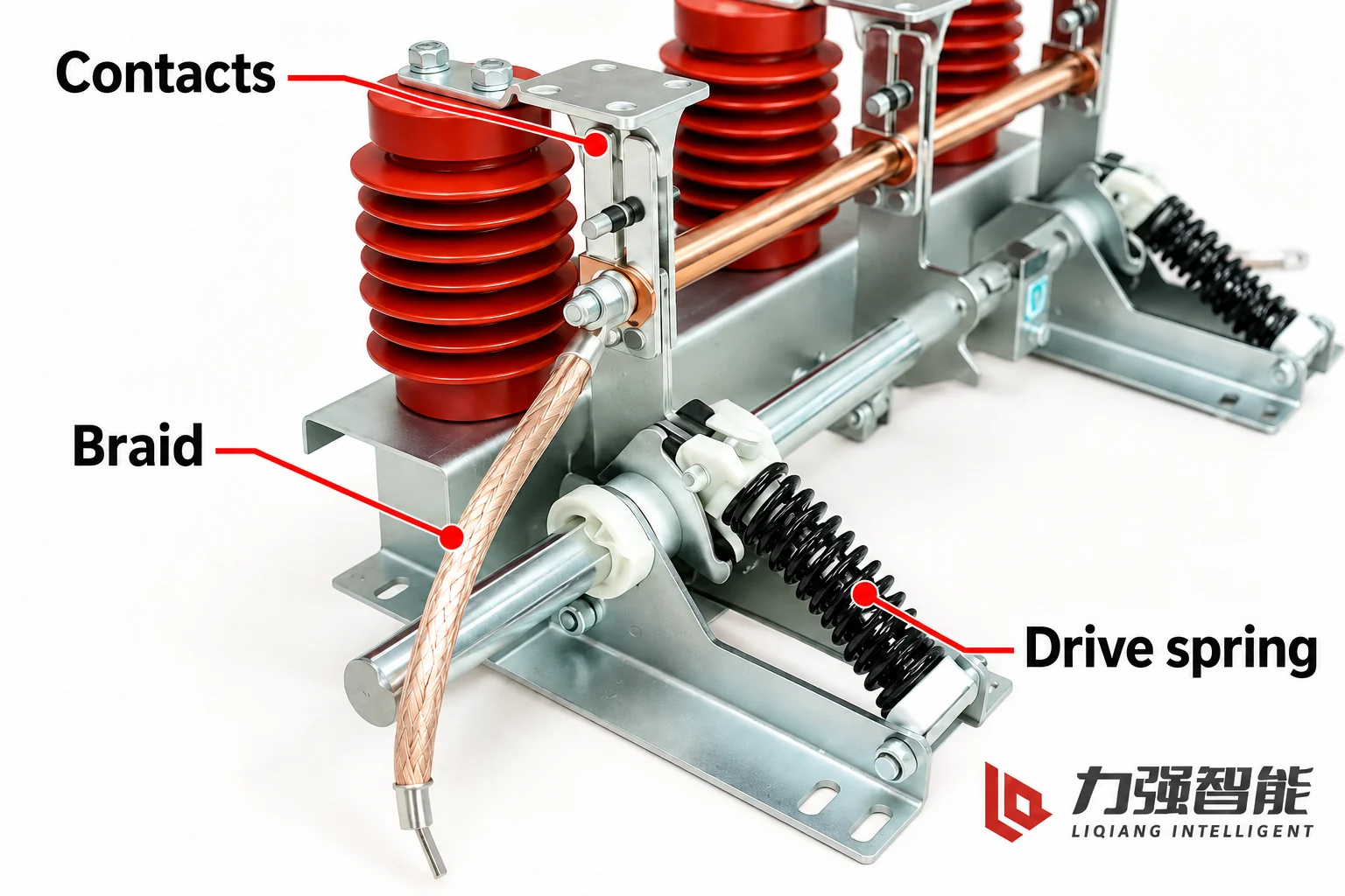
The contact group, flexible conducting connection and stored-energy drive spring cooperate through different electrical and mechanical roles.
The conducting arrangement is the group that carries current through the device to its earthing terminations. The manual groups the flexible connection and the collecting tube as conducting parts of the earthing arrangement. The flexible connection is a braided copper shunt: it can accommodate the small movements between parts without becoming a rigid link, while remaining a conductor. The collecting tube runs across the assembly. Both are visible in the photograph, together with the end-mounted crank and spring components.
The locating and driving group holds the parts in their proper relative positions and produces the motion. The base frame and the post insulators place the live parts where they belong and take the mechanical loads that follow; the main shaft, the crank and the stored-energy spring turn an operating input into blade travel; the adjusting and positioning ring sets the geometric relationship between linked parts rather than conducting or driving in any primary sense.
The blade both moves and conducts. The flexible connection accommodates movement while maintaining an electrical connection, and the contact spring supplies the pressure needed at the conducting interface. Mechanical and electrical roles therefore cooperate within the same assembly.
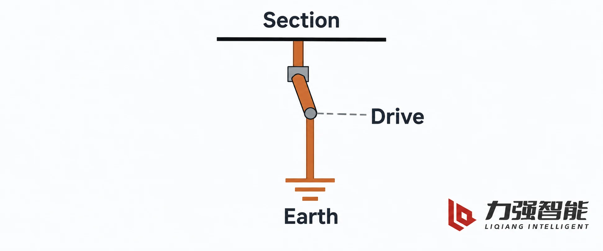
Closing the earthing contact connects the selected section to its designated earth path. The mechanical drive moves the contact, while the solid conducting route carries the electrical connection.
The fixed contact connects to the selected circuit section. When the blade engages it, the blade joins that section to the device’s conducting arrangement and intended earth connection. The flexible connections and collecting tube maintain the specified conductive relationships between those parts. At the installation interface, the device’s earth connection joins the earthing system. This explains the function without assuming that every design uses a return path through its frame or operating shaft.
Open and closed: what changes at the contact
In the open position the blade is separated from the fixed contact. The earthing connection does not exist, and the section is not tied to earth through this device. In the closed position the blade rests on the fixed contact under the pressure of the contact spring, and the intended connection is established.
The manual’s mechanism description explains how the closed relationship is achieved: the operating input is transmitted to the main shaft and crank, and the stored-energy spring releases to drive the earthing blade toward the fixed contact; in the closed position the blade makes reliable contact with the fixed contact through the contact spring. The stored energy matters because contact engagement has to be fast and definite rather than dependent on how the operator happens to push. This is not unique to earthing switches — it is the same engineering reason stored energy appears in any device whose closing behaviour must be repeatable.
It is worth being exact about what a contact position establishes. A separated blade is a definite open position of the earthing connection: the section is not earthed through this device. It does not follow that the section is isolated, and it certainly does not follow that the device interrupted anything. The earthing function is fundamentally a closing-and-carrying duty. Whether a given device has any breaking assignment at all is a separate question answered by its rating table, not by the fact that the blade can move.
Short-circuit making is a closing capability
Short-circuit making is the assigned ability to establish short-circuit current during closing under stated conditions. For an earthing switch, closing the earth connection onto an energized section can itself establish an earth fault; a fault does not have to exist before the operation. As the contacts approach, a prestrike arc may establish current before metal-to-metal contact. The contacts must then engage and hold while carrying the resulting current and resisting the associated electrodynamic forces.
Everything the device is made of is loaded at that instant. Contact surfaces are eroded by the arc and subjected to the forces that try to push the blade off the fixed contact; the blade, the shaft and the drive see a sudden mechanical load; the contact spring pressure, the closing speed and the mass of the moving parts all determine how much damage is done before the contacts settle. That is why stored-energy closing and generous contact pressure are used, and why a making rating is a statement about the whole closing assembly rather than about any one part.
It is also why the rating cannot be inferred from the mechanism. A spring is a mechanical component: it shows how the closing motion is delivered, not what current the device may be asked to establish. The JN15 table lists short-circuit making as its own field alongside the two stability fields, which signals that it is a separately assigned duty. ABB’s NAL/NALF catalogue handles earthing devices the same way at a different scale — its earthing-switch table lists short-circuit making for some versions together with the applicable conditions, and differs between versions; the making-and-breaking entries on the same catalogue’s switch-fuse combination table belong to a different rated object and cannot be read across to the earthing device.
The practical consequence is a capability statement, not a permission. Where a version carries an assigned making rating, it can be selected for a duty that includes withstanding a close onto a fault. Where no making rating is stated for the version, nothing about the device supports the assumption that it can.
Short-time and peak withstand describe different stresses
Once the current is established, the demand shifts from making it to holding it, and the two withstand duties answer two different questions.
Short-time withstand is stated as a current together with a duration, and the duration is part of the specification rather than an accompanying note. The reason is heat: the energy deposited in the contacts, blade, flexible shunt, collecting tube and terminals depends both on how much current flows and on how long it flows. The same current held for a longer period raises the temperature of those parts further, because the material available to absorb heat and the surfaces available to shed it are finite. The rating states the current-and-duration duty the complete arrangement is assigned to withstand. It is not a direct prediction of the exact time at which that device reaches a thermal limit under every fault condition.
Peak withstand addresses a different event: the highest instantaneous current the device must survive during the fault, which can be considerably larger than the steady value of the fault current. At that instant the forces between current-carrying parts vary very steeply with current magnitude — far faster than proportionally — and they act to push the contacts apart, bend the blade, pull on the flexible connection, load the insulating posts and stress whatever the assembly is mounted on. The qualities that resist it are exactly the mechanical ones: contact spring pressure, blade stiffness, the strength and spacing of the supports, and the rigidity of the frame. A device can therefore have ample thermal capacity and still be pulled apart by a high instantaneous peak; that asymmetry is why the two figures are stated separately.
The three duties are not convertible into one another. A stated short-time current and duration do not by themselves specify the peak withstand or making duty. The fields describe related short-circuit demands, but one cannot replace another without the applicable ratings and conditions. Treating any two as interchangeable by assumption produces the same error as reading a making rating out of a withstand figure.
Making establishes current during closing. Short-time withstand includes current and duration, while peak withstand addresses instantaneous stress on the closed arrangement.
Applying the earthing function to a defined cable section
Consider an indoor switchgear project: a single feeder bay in a metal-enclosed medium-voltage board, where the outgoing cable is a three-core XLPE run to a downstream package substation. The requirement that drives the layout is that this cable section must be separated from its supply boundary and connected to the intended earthing system for maintenance at its cable terminations. Three separate tasks follow from that one requirement, and they are handled by three different arrangements in the bay.
The interruption duty belongs to the circuit breaker: it is the device that opens a flowing current, load current in normal service and fault current under fault conditions. The isolation duty belongs to a disconnecting function — a separate disconnector, or the disconnecting position of a three-position switch-disconnector — which creates a defined break in the supply path so the cable section no longer depends on the breaker alone. The earthing duty belongs to the earthing switch, which closes onto the cable side and connects that section to the installation earth. ABB’s Uniswitch manual illustrates precisely this allocation for one fixed circuit-breaker bay: a three-position switch-disconnector sits between the busbar and the breaker, and an earthing switch is provided on the cable and current-transformer side of the breaker. One functional arrangement, with the three jobs in three places.
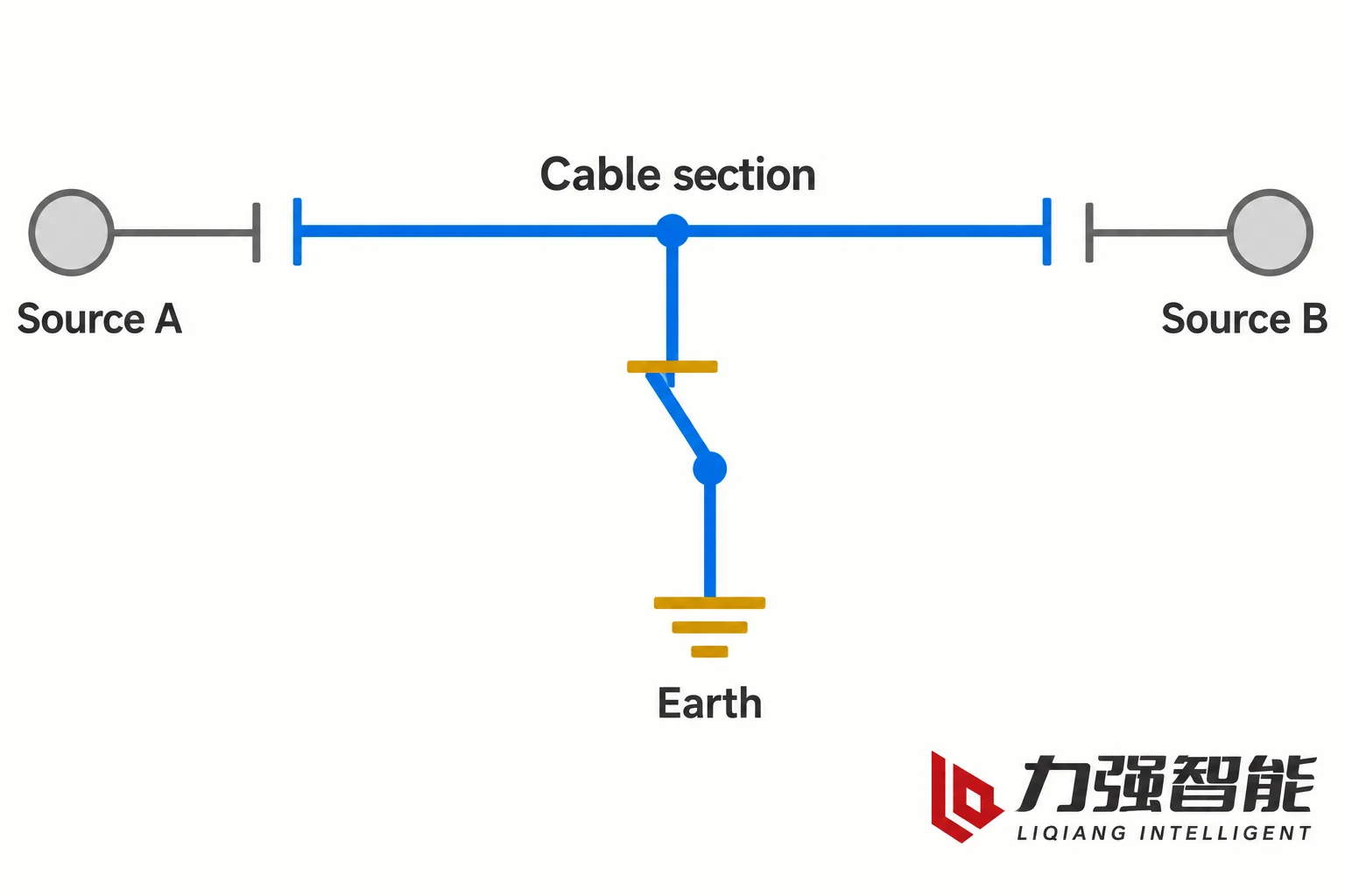
That example shows how the division works; it is not a wiring diagram for the JN15 and not a mandatory layout for every cabinet. The allocation moves when the conditions move. If the cable section can be fed from a second source, its supply boundary is no longer one device — isolation may need to happen at two places before the section is genuinely separated — while the earthing switch still earths only the section it is connected to. A busbar-side earthing point instead serves the parts still electrically connected to that point. A cable separated from it by the designated open contacts needs its own intended earth connection. If the incoming arrangement changes from a single feeder to a ring, or the panel order in the board is revised, the same device model may end up serving a differently bounded section. This is why “earth the selected cable section” is a more precise and more useful instruction than “earth the enclosure”: the enclosure contains busbar, breaker, current transformers, cable terminations and control wiring, and only part of it is connected to the earthing switch.
With two possible supply connections, the selected cable section has two supply boundaries. Its earthing connection serves the section still electrically connected to that point.
Position information, voltage information and the work arrangement
Three things get confused with one another in this area, and they are worth separating once and clearly. The first is the contact position of the earthing switch itself: the blade is against the fixed contact or it is not. That is a fact about the device’s own linkage, observable mechanically and reportable through position indication or an auxiliary contact. The second is voltage information, which is a separate measurement function. The JN15 manual lists voltage-display equipment and auxiliary switches among the items that can be supplied according to the user’s requirements — the selected version determines which items are fitted and how they are connected. The third is the installation and work arrangement as a whole: which section is involved, where its supply boundaries are, and what the work party intends to do.
The first two are inputs to a judgement; neither is the judgement. A closed earthing switch ties its own section to earth. A voltage indication reports what its own sensor sees at its own point. The state of a complete working area is established by the arrangement of the whole installation, not by reading one device in it.
Where to continue
For the construction and configuration of the indoor device described here, the JN15-12 indoor earthing switch page is the direct entry point, and the disconnector and earthing switch family covers the wider range. Matched manuals and drawings are collected in the downloads library, where the document version that applies to a specific configuration can be identified.
If the residual question is about the isolation function rather than earthing — what a disconnecting gap is, and where its boundaries lie — the explanation of what a disconnector is takes that task. If the question is about other rating fields beyond making and the two withstand duties, such as insulation levels or continuous current, the medium-voltage switching device ratings article covers the wider set. For a complete project decision that combines function, ratings, installation and control, the guide to selecting medium-voltage switching devices is the appropriate next step, and the switching devices explained overview shows where interruption, isolation and earthing sit relative to one another in a bay.
FAQ
Which current ratings should accompany an earthing-switch enquiry?
State the required short-time withstand current together with its duration, the peak withstand duty, and any required short-circuit making duty. Keep each field attached to the selected device version and its conditions. These fields describe different demands on the earthing arrangement; the normal load-current rating of a neighbouring breaker or load switch does not supply them. Include the section to be earthed and the installation’s mechanical interfaces so that the electrical duties belong to a usable configuration.
Why does the JN15 assembly use a flexible copper connection?
The braided connection maintains an electrical connection while accommodating movement between the parts it joins. This lets the conducting arrangement work with the moving earthing blade rather than relying on a rigid connection across that movement. The collecting tube and flexible connections form parts of this conducting arrangement, which joins the device’s intended earth connection to the installation earthing system.
Does a voltage indicator confirm the position of the earthing contacts?
No. A voltage indicator reports the voltage information available at its sensing point. A position indication or auxiliary contact instead reports the relevant mechanical position. The JN15 manual offers voltage-display equipment and auxiliary switches according to the selected requirements, so the fitted configuration determines which information is available. Neither indication alone describes all supply boundaries or the state of a whole working area.
Share your love
William Xiaonan Liu
William Xiaonan Liu writes for LIQELE about medium-voltage switching equipment, including vacuum circuit breakers, load break switches, disconnectors and earthing switches. His articles explain product selection, installation interfaces, operating requirements and technical documentation, helping switchgear builders and project buyers identify the information needed for equipment selection and supplier discussions.