Medium-Voltage Switching Device Ratings Explained: Voltage, Current, Breaking, Making and Withstand Duties
Approx. 15 min read
Quick Takeaway
Rated voltage and insulation withstand describe different assignments. In Liqiang’s VS1 manual, 12 kV rated voltage, 42 kV power-frequency withstand for one minute, and 75 kV peak lightning-impulse withstand are not three alternative continuous operating voltages.
Continuous current concerns temperature rise under the stated service conditions. Breaking ends an existing current, making establishes current during closing, and short-time and peak withstand describe different stresses on a closed device. Equal carrying amperes do not establish equal fault duties.
Keep the rated object, quantity and conditions together. RMS, instantaneous peak and duration are different quantities; a fuse breaking field does not become a bare-switch rating, and a coordinated combination retains its specified fuse and assembly conditions.
A switching-device rating is a statement about how one defined piece of equipment handles one specified electrical stress or one specified switching task, under stated conditions. It is not a single capability score. A device may be asked to carry normal current for years, to end an existing current, to establish current by closing a connection, and to stay thermally and mechanically intact while a fault current passes through it until something else clears that fault. Those are four different demands, and they act on parts that physically overlap.
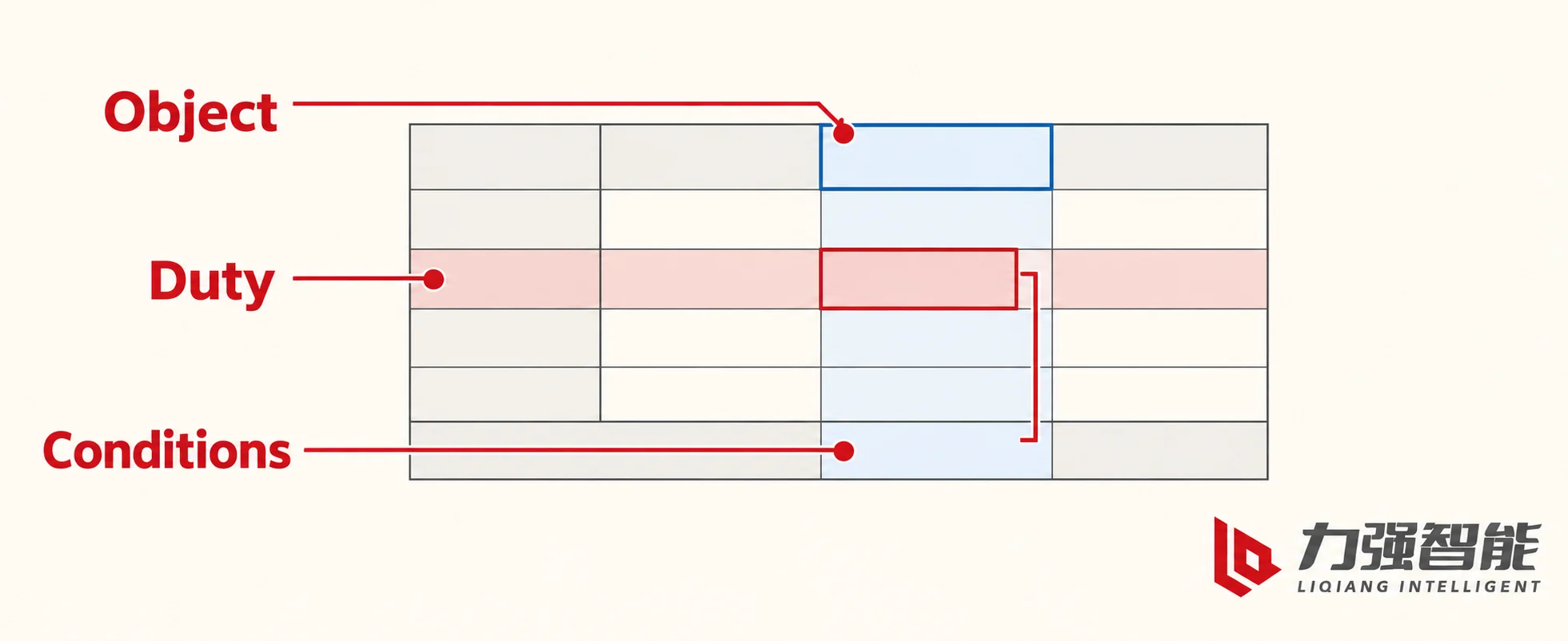
Three questions keep a ratings table readable. First, which object is rated: a bare switching device, an interrupter inside it, a fuse, a coordinated switch-fuse combination, or a complete cabinet. Second, which electrical task the field describes. Third, under what conditions. The field name and its unit answer the second question; footnotes, reference fuse designations, duration columns and paired column entries answer the third. A number separated from its heading stops being information.
Read a rating at the intersection of its object column and duty row, keeping the applicable conditions attached to that entry.
Voltage rating and insulation withstand are different assignments
Voltage appears in a ratings table as a classification. The nominal voltage of a network describes the operating context; the rated voltage assigned to a piece of equipment provides a reference for its specified operating and dielectric duties. Liqiang’s VS1(ZN63)-12 installation manual states a rated voltage of 12 kV and, in the same table, two separate insulation duties: a rated short-time power-frequency withstand voltage of 42 kV held for 1 minute, and a rated lightning impulse withstand voltage of 75 kV peak.
Those three numbers are not three alternative working voltages, and neither 42 kV nor 75 kV is a continuous operating voltage. They describe different dielectric stresses across the specified insulation paths.
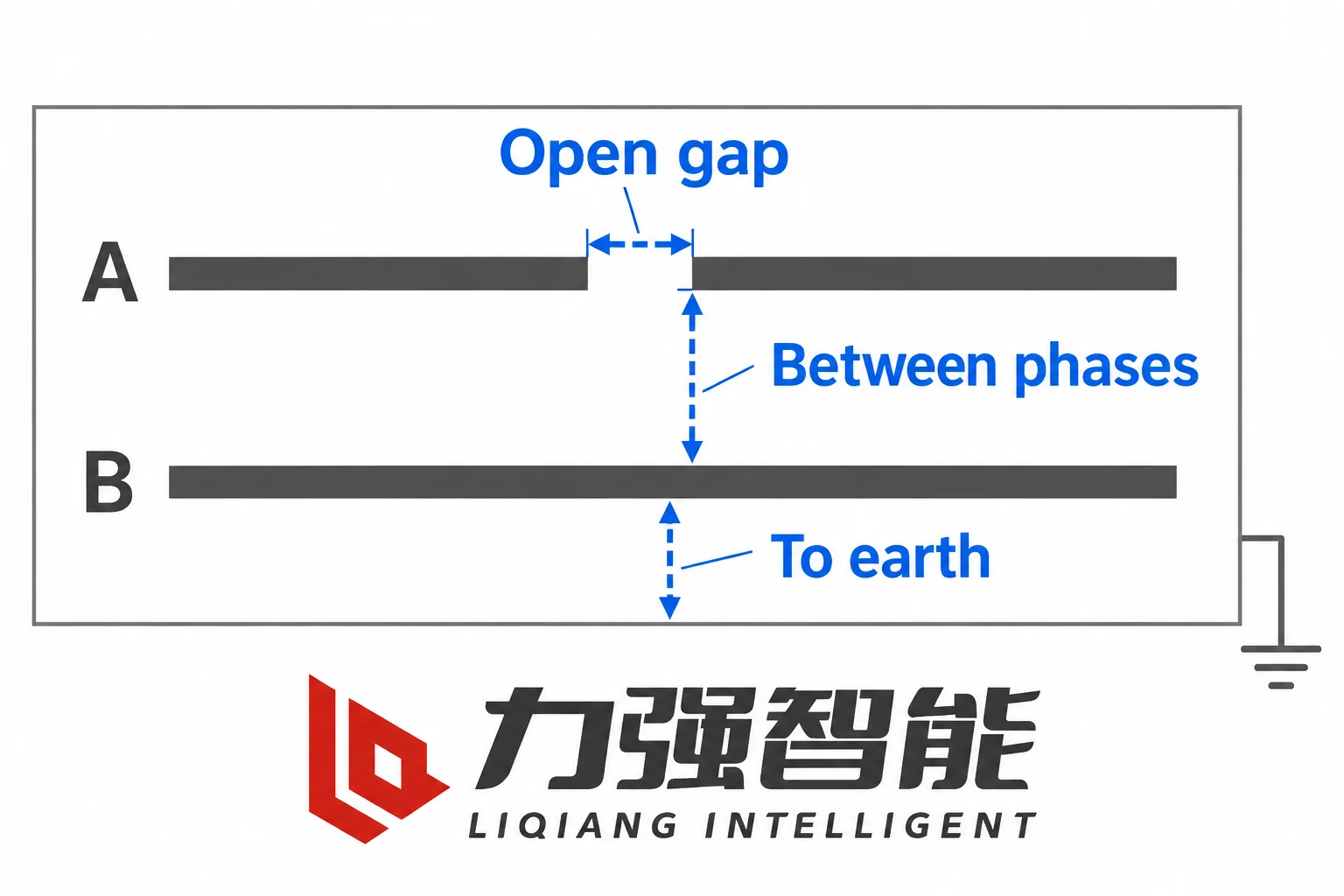
Insulation is stressed wherever an electric field crosses a dielectric path. In a three-phase device there is a path from each live part to earth, a path between phases, and, when the device is open, a path across the open contact gap. A cast-resin embedded pole, an air clearance inside a metal enclosure and a gas-filled compartment are all ways of holding that field on whichever path applies. This is why the same voltage class can look physically very different from one installation to another: pollution, humidity, altitude, clearances and the enclosure arrangement all change how much insulation distance and what construction are needed.
Power-frequency withstand is a sustained dielectric duty. A defined alternating waveform is applied at the stated voltage for a stated time, one minute in the VS1 table. It tests dielectric strength under sustained AC stress; the specified duration is part of that duty. Lightning impulse withstand is a transient duty: a short, fast-fronted wave defined by its shape and its peak value, 75 kV here. It addresses fast-front overvoltage stress rather than continuous AC operation. The waveform, the peak and the insulation arrangement under test all belong to the field.
Once the duties are separated, it is no longer surprising that a withstand test value is several times the assigned operating voltage. Insulation has to survive the overvoltages the network actually imposes, and it has to do so with margin while it ages slowly in service. A rating of 42 kV for one minute of power-frequency stress is a statement about dielectric strength under a defined test waveform, not a second operating voltage.
Dielectric duties can concern phase-to-earth separation, separation between phases, or the open gap within one phase. The blue brackets identify these different paths.
Continuous current is a temperature-rise duty
Current through a conductor produces heat. Inside a closed switching device, heat is generated in the bulk of the conductor, at the contact interface where a small contact resistance remains even when the contacts are properly closed, and at terminal and joint connections. The loss therefore depends on details that a single ampere figure hides: contact design and contact pressure, plating and surface condition, conductor cross-section and geometry, and the number and quality of joints along the current path.
Heat leaves by an equally practical route. Conduction carries heat along connected conductors and terminals. Convection transfers heat to the surrounding air, while radiation transfers heat to nearby surfaces. The enclosure and its ventilation affect how that heat reaches the room. Ambient temperature, air movement, enclosure volume, ventilation and the presence of neighbouring warm devices all change how much heat can leave. The continuous current rating is therefore best read as a temperature-rise duty: the current the device can carry indefinitely while the temperatures of its contacts, conductors, joints and insulation stay within their limits under the service conditions assumed by that rating. The limit is not only the contact temperature; insulation degrades at temperatures far below what a contact or a joint can survive for a few seconds.
Two consequences follow. First, a device rated for 630 A continuous is not thereby able to pass a much larger current briefly. The ampere figure is a steady-state thermal statement, not a short-time one. Liqiang’s VS1 table includes a 630 A current configuration, and the FKN12-12D/630-20 row in the FKN12 manual lists 630 A rated current together with a 630 A active-load breaking field. The two rated-current entries support a comparison of carrying duty. The FKN12 active-load breaking entry separately states a particular interruption duty; it does not assign short-circuit breaking to the bare switch.
Second, one physical part usually carries several responsibilities at once. A contact carries current, conducts heat away from the contact interface, transmits closing force, and resists electrodynamic force during a fault. A pole housing supports conductors, insulates phase from earth, guides mechanical motion and may also form part of a heat path. The useful question is which stresses those cooperating parts see in each duty.
Breaking and making put different demands on the contacts
Breaking starts from an existing current and has to finish with an open circuit that stays open. Separating the contacts is a necessary step, but it is not the interruption.
The physical obstacle is the arc. Siemens’ GM-SG medium-voltage switchgear guide describes it in its vacuum interrupter principles: when the contacts are drawn apart, a metal-vapour arc forms and current continues to flow through that plasma. In successful AC interruption, the arc extinguishes around current zero, the vapour condenses, and the gap recovers dielectric strength quickly. The device must then withstand the recovery voltage that appears across that gap as the circuit voltage re-establishes itself. Interruption therefore needs arc management inside the interrupter, interaction with the current zero, and fast dielectric recovery in the gap, on top of the mechanical movement that started the process. A mechanism that opens contacts is not by itself evidence that current was successfully interrupted and that the open gap will hold voltage afterwards.
Breaking duties differ by circuit as well as by current magnitude. ABB’s NAL/NALF switch-disconnector and switch-fuse catalogue keeps separate fields for active load switching, closed-loop switching and charging current switching, which is a practical reminder that interrupting a given current under one circuit condition is a specific task rather than a general ability. Short-circuit breaking is a further step: the current can be much larger, may contain a decaying direct-current component, and can impose a different recovery-voltage duty. A device that is rated to break load current holds a load-breaking duty; a fault-interruption duty has to be stated separately, for a defined object, at a defined voltage.
Making, or closing, encounters different physics. The contacts move toward each other and, before they touch, an arc can bridge the last small gap; current then transfers into solid contact while the contacts are still settling and the contact force is still building. If the circuit is closed onto an existing fault, a high initial peak can pass through the contact system while contact engagement and force are developing. The electrodynamic forces grow with the square of the instantaneous current for a given geometry. Depending on the contact and conductor arrangement, they can oppose contact pressure or load the conductors and their supports while the mechanism closes. Making ratings describe that combination: establishing the connection while the specified current, including its first peak, flows.
Closing and latching terms follow the object they are defined for. A closing-and-latching field on a circuit breaker is a stated duty of that breaker. It is not a universal label that transfers onto a switch, and a device that can close a circuit is not automatically rated to close onto a fault.
Continuous-current carrying depends on heat generation and the available heat removal under the surrounding and installation conditions.
Short-time and peak withstand describe heat and force
The two withstand ratings describe what a closed device survives, and they are kept apart because heat and mechanical force scale differently.
Short-time withstand current describes the current a closed device can carry for a stated time without damage under the assigned conditions. During that interval it carries the current; the protection arrangement determines when and where interruption occurs. A breaker may withstand a delayed-clearing interval before it opens, while a switch or busbar may depend on a separate breaker or a coordinated fuse. ABB’s tables pair this current with specific durations such as 1 s, 2 s and 3 s, and that pairing is part of the rating rather than an illustration. During the exposure, heat is generated in the contact interfaces, the joints and the conductors, and part of it conducts into supports and insulation. Which parts actually get hot, and how much heat escapes during the interval, depends on the construction and on how long the interval is.
Peak withstand concerns the highest instantaneous value of the current, and it is a mechanical statement. The force between current-carrying conductors rises with the square of the instantaneous current, so a high initial peak can impose a strong mechanical load early in the fault. That force acts on busbar sections, contact supports, flexible connections and moving parts, bending and pulling at them. Where these forces tend to separate contacts, contact pressure and the holding arrangement must resist them.
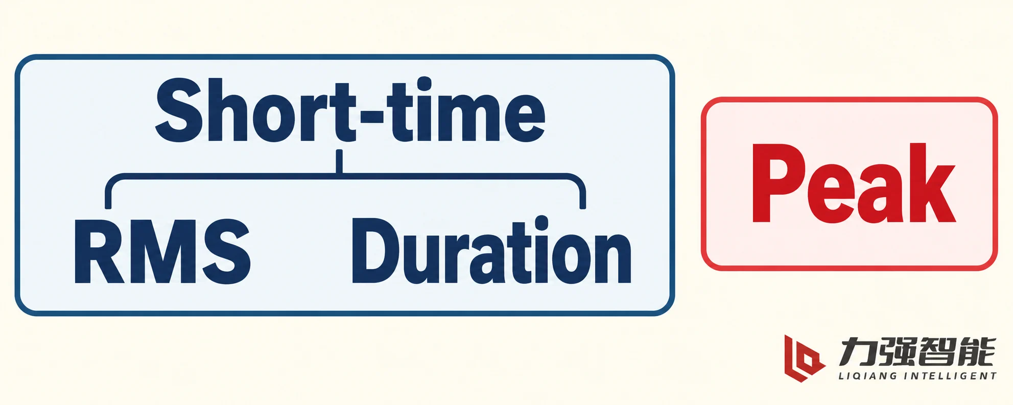
The two fields cannot substitute for each other. A large peak value says nothing about how long a device can carry heat, and a short-time value without its duration is an incomplete rating, because one second and three seconds are different duties. The stated duration is a rating condition, not a suggested protection-delay setting, and it is not a licence to rescale every rating with a current-squared-times-time relationship. Over a longer exposure, more heat has time to leave the conductors, so the simple adiabatic relationship between current, time and temperature rise no longer holds exactly. Deciding which protective device clears a fault, and in what time, is a protection-design task that starts from these ratings instead of replacing them.
RMS, peak current and duration are different quantities
Alternating current changes value continuously, so a rating has to say which quantity it quotes.
The effective, or root-mean-square, current is the value of direct current that would produce the same average heating in a given resistance. This makes RMS useful for describing continuous heating. Breaking ratings also commonly use RMS to specify the relevant AC current quantity, but interruption additionally depends on arc behaviour, any asymmetry and recovery voltage. It is not the arithmetic average: a symmetrical alternating quantity averages to zero, yet it certainly heats a conductor, which is exactly why the average is useless as a heating measure.
Peak current is the largest instantaneous magnitude reached, regardless of sign. It is the quantity that matters where mechanical effect is the limiting factor, which is why peak withstand and some closing fields are quoted as peaks. Duration states how long the exposure lasts, and it belongs to whichever quantity the field quotes.
Real fault current complicates the arithmetic. A fault is fed through a network containing inductance as well as resistance, so, depending on the instant the fault begins, the current can include a direct-current offset that decays according to the circuit’s inductance and resistance. The first peak is therefore not a fixed multiple of the effective value, and a generic sinusoidal ratio cannot convert every current label from one form into another. Schneider Electric’s electrical distribution design guide, in its medium-voltage circuit-breaker definitions, distinguishes the effective value of the symmetrical breaking component from the total effective value that includes the asymmetrical component, and its tables quote closing and latching current as a peak value in the same set of definitions. Treating those quantities as interchangeable is a common source of wrong comparisons.
Different standards families also group these duties differently. Publications in the IEC tradition and in the ANSI/IEEE tradition name and arrange rating fields in their own ways, with different table structures and qualifiers. Rather than mapping a field onto whichever familiar term sounds closest, the useful habit is to carry the duty, the quantity and the conditions across intact.
An RMS short-time current and its stated duration form one specified duty. A peak value describes a different quantity with its own applicable conditions.
Why two 630 A devices can serve different feeder duties
For an industrial 12 kV switchboard, compare a breaker candidate and a load-switch candidate whose tables each include a 630 A carrying field. That common device rating can make them look similar at first glance, although a breaker bay and a transformer branch using a switch-fuse arrangement allocate duties differently. The usable continuous current of the complete switch-fuse arrangement also depends on its selected fuse and assembly rating.
One bay is equipped with a circuit breaker. That breaker is assigned the switching of the branch, the interruption of fault current at that point, closing onto the branch with the specified making duty, and short-time and peak withstand while a downstream protection clears a fault.
The other bay uses a load-break switch with a current-limiting fuse. Here the tasks are divided. The bare switch performs the switching duties it is rated for, such as load current and whatever closed-loop or charging duties its documentation states. The fuse takes the short-circuit interruption, in the current range and under the conditions for which that fuse is specified. The two together form a coordinated combination with its own rating, valid for a defined fuse type and defined conditions.
This division of labour is visible in the tables. In Liqiang’s FKN12 manual, the FKN12 bare switch columns and the FKRN12 switch-fuse combination columns are separate, and the row stating a short-circuit breaking current names a current-limiting fuse. That field explicitly identifies the fuse component; the coordinated combination needs its own applicable rating and conditions. It does not travel back to the bare switch, and it does not by itself establish the rating of every cabinet the switch might be installed in. ABB’s catalogue approaches the same logic from the other side: a complete switch-fuse combination table is published separately from the bare switch table and is qualified by specified reference fuse links and named applicable conditions.
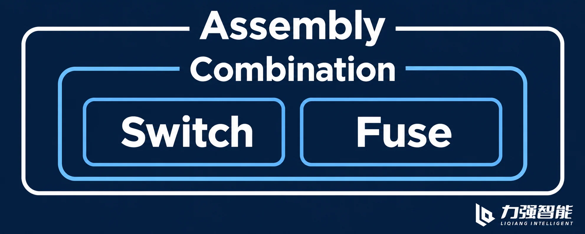
A cabinet is itself an object larger than any of its components. Enclosure dimensions, busbar and connection interfaces, the mounting arrangement of the switch and the fuse, clearances and ventilation all take part in what the assembled unit can carry and withstand. A component rating that is more generous than the assembly does not raise the assembly’s rating, and an assembly rating does not automatically apply to a different combination of parts.
Now change one condition. Suppose the substation is reinforced and the prospective short-circuit current at the 12 kV busbar rises, while the branch load and installation conditions remain unchanged. The continuous carrying requirement has not increased, but that does not establish suitability for the new fault duty. Everything else needs a fresh reading: the fault interruption the bay is credited with, the making duty the closing contacts will meet, the short-time withstand with its duration, and the peak withstand against a larger first peak. In the switch-fuse bay, the combination may still be valid with the same reference fuse, or the specified fuse and its conditions may no longer cover the new fault level. That is a question about the combination and its conditions rather than about the switch carrying amperes.
This is the practical reason two 630 A devices are not interchangeable descriptions of each other. The carrying number describes temperature rise in service. The fault level and the protection arrangement decide which device is assigned which switching and withstand duty.
The switch, fuse, coordinated combination and complete assembly are different rated objects. The combination depends on its specified components and conditions.
From ratings to a device or protection arrangement
The VS1-12 and FKN12 pages lead to the equipment used in these examples. Matching manuals and drawings are grouped in the product document library, where the field meanings can be applied to a particular configuration.
Can a higher short-time withstand current compensate for a lower breaking rating?
No. Short-time withstand describes carrying current while the device remains closed for the stated interval. Breaking describes interrupting an existing current and withstanding the recovery voltage across the resulting gap. A larger carrying value does not supply a missing interruption capability. The protection arrangement must allocate interruption to an appropriately rated device while the other connected equipment meets its own assigned withstand duty.
Can a 1-second withstand rating be converted into a 3-second rating?
There is no universal conversion that applies to every device. Current and duration form the assigned duty together, and changing the duration changes the heating exposure and the opportunity for heat to leave the conductors. A simple current-squared-times-time relationship does not establish all thermal and mechanical limits of a complete assembly. Use the applicable current-and-duration assignment for that version, keeping peak withstand and making duty as separate fields.
Which ratings need another look when the fault level rises but the load stays the same?
Reassess the assigned fault-interruption duty, making duty, short-time withstand current with its duration, and peak withstand. In a switch-fuse arrangement, the specified fuse and combination conditions also matter. The continuous carrying requirement may stay unchanged when the load and installation conditions do, but that alone does not establish suitability for the new fault duty.
Share your love
William Xiaonan Liu
William Xiaonan Liu writes for LIQELE about medium-voltage switching equipment, including vacuum circuit breakers, load break switches, disconnectors and earthing switches. His articles explain product selection, installation interfaces, operating requirements and technical documentation, helping switchgear builders and project buyers identify the information needed for equipment selection and supplier discussions.