Outdoor Circuit Breaker or Complete Recloser System? Define the Supply Boundary
Approx. 19 min read
Quick Takeaway
Define a complete recloser supply by its declared sensing, decision, trip/close, feedback and lockout functions; a motor and a compatible-looking connector do not establish that system.
Check controller power, operating energy, replenishment and backup separately: a live controller cannot prove the selected drive is ready or that a command changed the contact state.
Assign every supplied, retained and site interface to a named owner, then require functional evidence for the exact primary unit, controller, settings and energy arrangement before closing the scope.
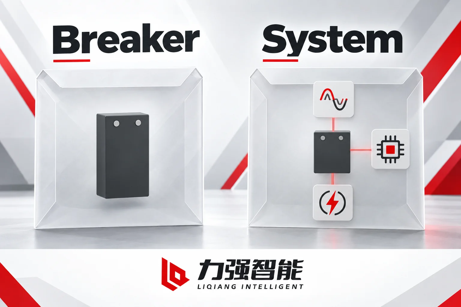
A primary switching unit and the functions around it have different supply boundaries. These abstract blocks represent roles, not actual product geometry or included accessories.
A motor-operated outdoor vacuum circuit breaker is a switching apparatus. It interrupts current; the selected mechanism and control circuit determine which electrical trip or close commands it accepts. In a motor-charged spring arrangement, the motor replenishes closing energy. None of that makes it a complete automatic protection and reclosing system. The difference is not a matter of accessories — it is a matter of which functions have actually been specified, matched, configured and evidenced as a working combination.
This article walks a project buyer through that distinction: what the primary unit provides, what must surround it before the supply meets a declared automatic protection or reclosing function, and how to write an enquiry and release scope that reflects the real boundary rather than an assumed one.
Define the Required Function Before Calling the Supply Complete
The starting point is a question the project team needs to answer before issuing an enquiry: what is the feeder actually required to do automatically, and under what conditions?
A primary outdoor vacuum circuit breaker provides the current-interrupting contacts, an operating mechanism and the interfaces specified for its configuration. The ZW20-12 and ZW32-12 families illustrate why the mechanism and interface package must be identified separately. The ZW20-12 product page describes the vacuum interruption chamber within an SF6/N2 mixed-gas insulated tank arrangement, with separately specified operation, disconnector, operating PT and controller choices. The ZW32-12 product page separates manual, electric spring, intelligent and permanent-magnet variants, and treats the CT/PT package, operating supplies and controller functions as selected fields in a designation rather than universal inclusions. Neither family name, by itself, establishes what protection logic runs, what reclosing sequence executes or what communications are active.
The outdoor family page makes this explicit: reclosing, fault protection and communications depend on the selected controller and feeder scheme; a photograph, motor operation or family name does not establish these functions.
“Complete” therefore means complete for the declared function and interface scope of a specific configuration — not complete in the sense of having every possible accessory fitted. A supply is complete as an automatic reclosing system only when fault sensing, the protection decision, the timed reclosing sequence, lockout and restoration logic are all present in the agreed combination and have been confirmed to work together. Local automatic reclosing does not inherently require communications; communications are a named option to include only when the project requires them. Equally, the ZW20 manual overview describes selected inrush, limited-close and overcurrent functions in a configured arrangement with an external voltage transformer and a separate controller, then explicitly directs the reader to the composite-controller instructions for that controller’s logic. That direction is the boundary: the breaker manual describes the mechanism and its interfaces; the controller handbook defines the protection logic.
When the project requires conformity to a particular recloser standard, request the exact primary-unit and controller combination, the applicable standard edition and the records covering that combination. A family designation or the inclusion of a motor does not establish this conformity.
Describe the Closed Loop from Measurement to Confirmed State
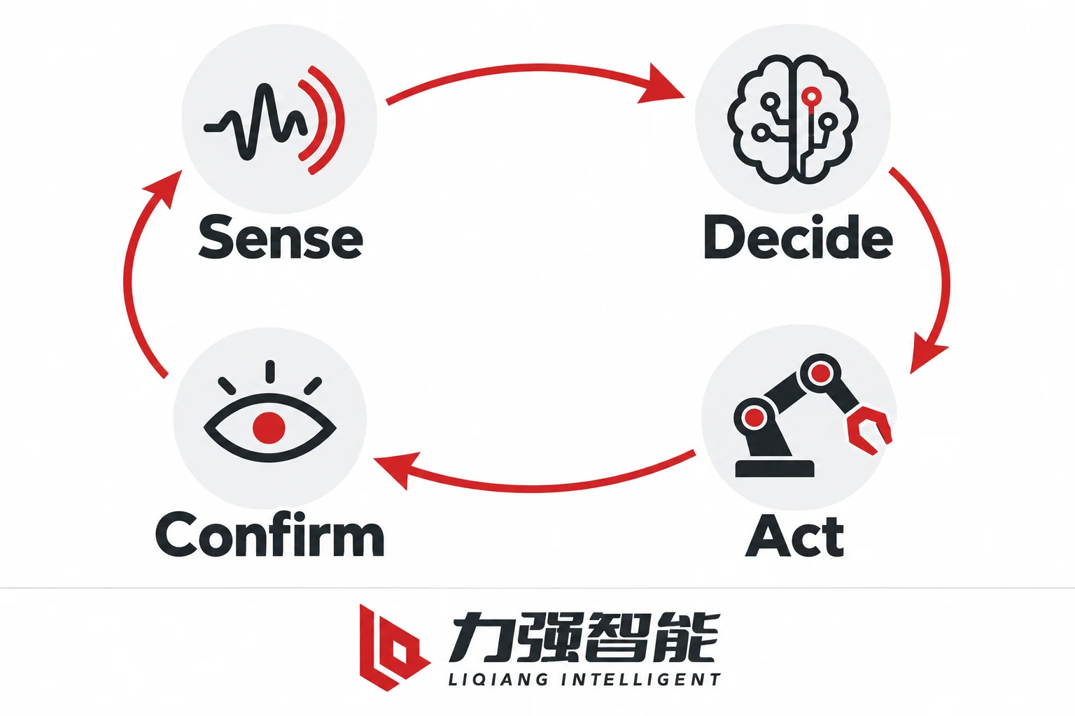
Distinguish measurement, decision, execution and actual-state feedback. This functional view is not a wiring diagram or an operating sequence.
Before asking whether a supply is complete, it helps to be precise about what a complete loop requires. There are four distinct roles: measurement input, protection and control decision, trip or close execution, and actual-state feedback. Each can be physically integrated with another or externally provided, but none can be assumed present just because another is.
Measurement is the acquisition of current, voltage or other electrical quantities on the feeder. In the ZW32-12 family, CT current outputs can feed an intelligent controller for information analysis and overcurrent protection decisions — the measurement function sits in the CT assembly, and the interpretation sits in the controller. The system needs a defined measurement path from suitable sensors to the decision function. Those sensors may be supplied with the primary unit or retained elsewhere in the installation; the order must identify which path is used and who confirms its compatibility.
Decision is the protection and control logic that evaluates measured quantities against thresholds, sequences reclosing attempts, counts lockout conditions and determines whether the next action should be a trip, a close or a final lock. This logic lives in the controller and its configuration, not in the mechanism. The ZW20 manual overview lists inrush and overcurrent functions in its described controller, and explicitly says to read the composite-controller instruction manual for that logic. The ZW32 manual describes protection, reclosing and communications as features of the intelligent controller configuration. For a project, obtain the selected controller documentation and approved settings to define the actual protection decisions, sequence count, timing and reset behaviour. A mechanism description cannot establish these functions.
Execution is the physical act of opening or closing the vacuum contacts. The ZW20 working-principle section makes the mechanism clear: the motor charges the closing spring, a limit switch removes motor power when charging is complete, and an electrical open or close command energises the corresponding actuator to release the relevant mechanism latch. The key point is that command issuance and contact movement are separate events. For the selected mechanism, execution depends on the required electrical and mechanical energy, a valid command and the applicable interlocks. An issued command is not confirmation that contacts moved.
Actual-state feedback is the evidence that a contact operation actually occurred — typically a position indication contact or auxiliary switch output that reflects the physical state of the primary contacts, not just the last command sent. If the expected response interval has elapsed and valid feedback still shows closed after a trip command, the system has an unresolved command-to-state discrepancy. The cause could lie in command delivery, an inhibited or failed operation, or the feedback path itself. A close command followed by open indication must likewise be interpreted with the response interval and any subsequent trip event. Define the automated feedback path and its validity separately from any local mechanical indication; a command log alone does not establish the post-operation contact state.
Two further requirements need definition as part of the system design: closing permission and readiness, and final lockout or reset behaviour. A close permissive represents the conditions required by the approved scheme before it allows closing; identify each condition and the input that establishes it. Mechanism readiness asks a different question: is the selected drive capable of the required action, including its energy requirements? Final lockout inhibits further automatic reclosing under the defined sequence conditions. Specify its indication and the authorised reset or re-arm path; a lockout flag alone does not prove that the contacts are open. These behaviours belong to the selected controller configuration and project protection philosophy.
Specify Energy Availability During the Required Sequence
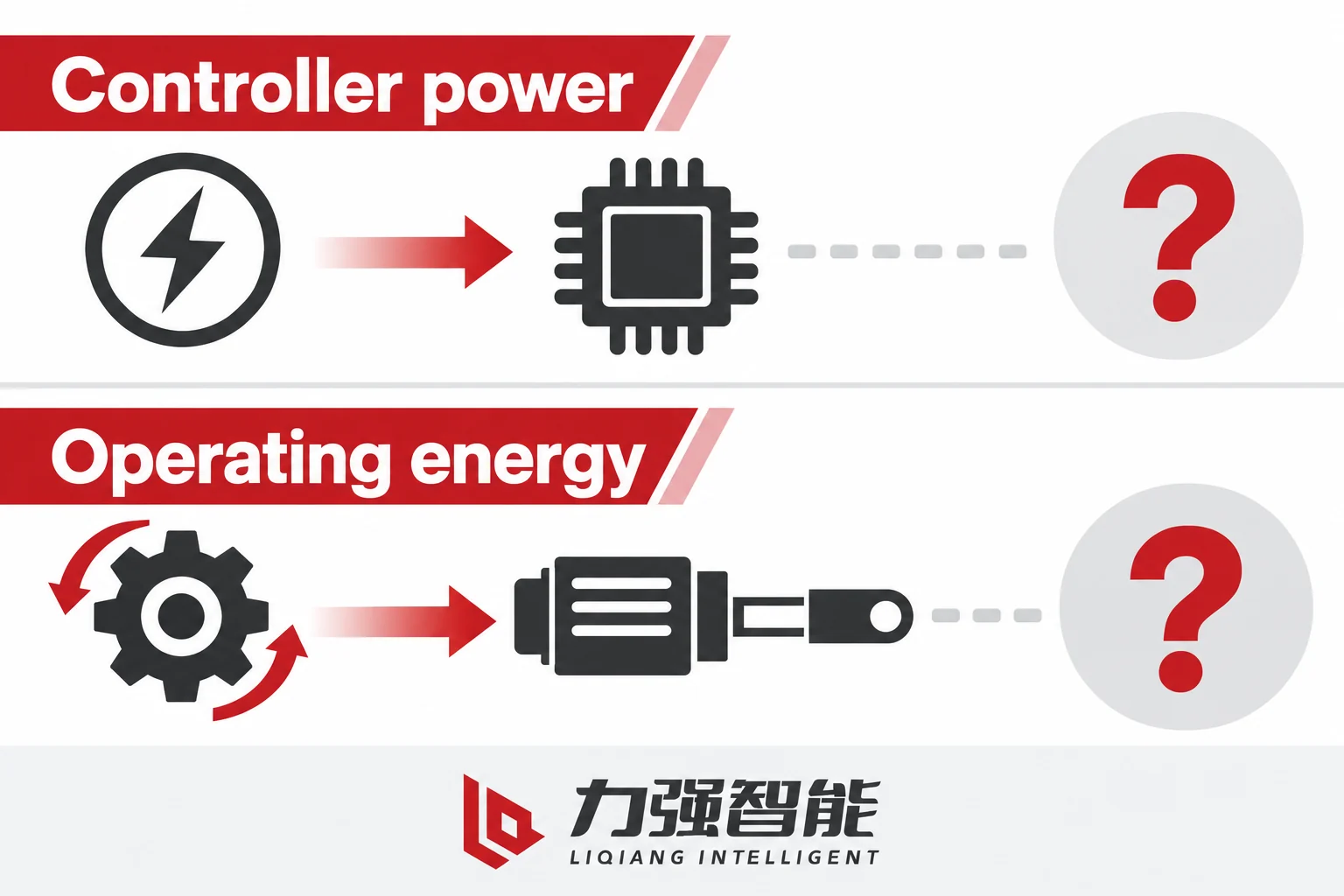
Controller power and available operating energy are separate readiness questions. The selected design defines their sources and behaviour.
Even a complete and correctly configured protection loop fails to perform its required function if the right energy is not available at the right moment. Separate the controller supply, the energy needed to initiate and complete each operation, the replenishment path and any required backup.
Controller supply is the power that keeps the controller’s electronics active: processing measurement inputs, executing decision logic, maintaining communications if fitted and presenting state indications. A controller that is alive and communicating is reassuring, but it does not tell you whether the mechanism can perform the next required operation.
Operating energy includes the electrical energy that initiates an action and the energy that moves the mechanism. In the documented ZW20 spring arrangement, the motor charges the closing spring until a limit switch removes motor power, and the closing actuator releases its latch when a valid close command is received. Opening uses its own mechanism path; the charged closing spring should not be treated as the energy source for every trip. The ZW32 offer also needs its actual drive identified, since the family includes spring and permanent-magnet variants.
For a spring-closing configuration, a further close requires adequate closing energy and replenishment between the required operations, whether charging is motor-driven or another designed provision is used. If a close request arrives before readiness, the scheme must define whether it is inhibited, rejected or otherwise handled. Do not assume that an unexecuted request will automatically operate the breaker when charging later completes. The required sequence must be assessed against the selected drive and its energy path.
Charging or replenishment supply restores the operating energy used by the selected drive; in a motor-charged spring arrangement it powers the charging motor. In the ZW20’s described arrangement the external voltage transformer serves both as a voltage measurement source for the controller and as the operating power supply. These are distinct purposes and must not be assumed interchangeable in every configuration. Losing the PT-derived supply during a fault sequence could simultaneously remove the measurement input, the controller supply and the charging motor supply — or only some of these, depending on how the actual system is wired and what backup is fitted.
Backup energy, if required, must be explicitly specified. Not every configuration includes an independent backup supply, and no universal backup architecture applies across the outdoor family. The project must state what behaviour is required on loss of the primary supply, on depletion of stored operating energy and on restoration of supply, and then verify that the selected configuration delivers that behaviour.
Eaton’s NOVA three-phase recloser instructions, MN280092EN, November 2018 distinguish compatible control-powered and auxiliary-powered versions, with different operating-energy paths and supply-loss provisions. This external example shows why the interface version, compatible controller and energy arrangement must be assessed together. For a LIQ order, specify and verify the offered arrangement on its own documents.
For any LIQ outdoor breaker project, the energy questions to resolve are: what powers the controller, what charges the mechanism, whether these are independent or shared, what happens if the primary operating PT or auxiliary supply is lost before or during a required sequence, and whether the specified backup — if any — has been confirmed present in the ordered configuration.
Allocate Supplied, Retained and Integration Responsibilities
Assign the supplied scope, interface reconciliation and integration responsibility explicitly for the project.
Once the required functions and energy conditions are defined, the next task is to allocate who owns each interface: who supplies it, who verifies it, and whose scope covers it if something is wrong.
Fill the matrix with named parties and actual document references. A blank owner or unresolved interface is an open action; purchasing a package does not silently allocate it.
Item / interface
Supplied, retained or excluded boundary
Named owner / handover
Record and verification to allocate
Gap / status
Primary unit and drive
Exact designation, duty and operating arrangement
Name supplier and accepting party
Applicable primary-device data and reports; match ordered configuration
Record any variant or duty gap
Current / voltage sensing
Included sensors or identified retained path; measurement versus supply role
Name sensing/interface owner
Sensor output and controller-input compatibility; approved drawing
Identify missing input characteristics
Controller hardware and configuration
Model, firmware and approved settings-file scope
Name configuration and approval owners
Controller documentation, settings reference and combined functional evidence
Resolve configuration/version mismatch
Commands and actual-state feedback
Drive interface, indication type, state reference and validity
Name each end of the interface
Matched circuit/interface documents and required response evidence
Close unknown signals or state definitions
Cables, connectors and power
Included assemblies, retained wiring, site feed and backup boundary
Name supply and connection owners
Approved interface revision and energy-availability assessment
Allocate any unprovided cable or supply
Mounting, earthing and site connections
Exact support and site-provided interfaces; communications only if required
Name installation and any network integration owners
Applicable installation requirements and site-interface verification
Resolve support, clearance or connection gaps
Combined integration evidence
Functions and exact combination covered by the supply
Name evidence provider and final integration owner
Required function, expected response, version and applicable record
Track each unresolved acceptance item
Two specific scenarios illustrate why this matrix matters more than a generic manufacturer-versus-buyer split.
Retaining a Controller While Replacing the Primary Unit
Suppose a feeder’s primary breaker needs replacement and the project proposes retaining its existing controller. The controller has previously been used with the same breaker family, and the connectors look similar. Retention may reduce the replacement scope, but it does not remove the need to reassess interfaces and the approved settings for the new combination.
Similarity is not compatibility. The following interfaces each need individual verification, not assumption:
Measurement interface: Does the new primary unit’s CT output match the input characteristics the existing controller expects? Ratio, burden, output type and connection scheme must be confirmed from the actual documents of both.
Command interface: Does the new drive’s trip and close interface accept the existing controller’s command type, drive voltage/current and duration? Match the required actuation energy and command timing to the selected interface; assess feedback separately.
State feedback interface: Does the new position indication match the controller input and the declared breaker-state reference? Distinguish a passive contact from an energised signal, and match contact state, circuit supply, load rating and any polarity requirements. Similar contact hardware does not establish the same circuit function.
Operating supply: If the controller was powered from the old PT arrangement, is the new PT compatible in output characteristics?
Firmware and configuration: Does the existing controller’s approved configuration file reference the old primary unit’s characteristics in any way that affects correct operation with the new unit?
Each of these is a specific document-to-document and drawing-to-drawing comparison, not a visual or family-level inspection.
Coordinated System Purchase
Now suppose the project purchases a coordinated package — breaker, controller, CT/PT assembly and cables from the same manufacturer under one order. A coordinated package can reduce separate interface handovers when one named party accepts responsibility for the matched scope. The remaining boundaries still need explicit allocation:
Site operating supply: Identify the connection point and which party provides each operating or auxiliary supply, including any PT-derived path. Record the required supply characteristics and backup scope; do not assume a separate external feed exists in every arrangement.
Site field wiring: List cables and terminations beyond the package interface and assign the responsible party for each connection to protection panels or other site systems.
Communications boundary: If communications are specified, name who provides the device-side interface, network, addressing and upstream integration. One packaged controller does not establish that all of these are included.
Approved settings file: Default settings do not establish feeder suitability. Name the competent party responsible for developing and approving the project settings and the party that confirms the loaded version for the actual combination before autonomous operation.
A coordinated purchase does not transfer all integration responsibility to the manufacturer. Internal matching still needs a named owner and applicable evidence, and each interface at the package boundary remains an explicit integration responsibility.
For family and installation comparison between the ZW20 and ZW32-12 families, including insulation type, mounting and project application context, see ZW20 vs ZW32-12 outdoor circuit breaker comparison.
Accept the Named Combination Against Its Functional Requirements
Tie acceptance evidence to the agreed expected response for the named configuration. These blank conceptual records claim no test result.
Before a supply is released for field installation and commissioning, there should be a record that ties each required function to an expected response and a documented source of evidence for that combination. Use the approved scheme to fill the expected response and acceptance criteria, then link the applicable factory or site evidence. The rows below identify the questions the evidence must answer.
Required function
Condition to define
Expected response from approved scheme
Combination / version
Record reference
Named owner
Unresolved gap
Required protection trip
Specified fault condition and enabled function
Required trip action and validated state feedback within its acceptance interval
Primary unit + controller + input path + settings version
Applicable combined functional record
Assign per project
Missing threshold basis, interface or response criterion
Automatic reclose, if required
Eligible trip, sequence timing and all required permissions/readiness
Required command disposition, drive action and confirmed resulting state
Drive, energy path and sequence configuration
Applicable factory / site functional evidence
Assign per project
Energy or replenishment capability for the required sequence
Inhibit and final lockout
Defined inhibit inputs or sequence limit reached
Automatic closing inhibited as specified; indication and reset/re-arm path defined
Controller configuration and relevant inputs
Configuration and functional evidence
Assign per project
Unknown input validity, indication or reset responsibility
Supply loss / depleted energy
Each relevant supply lost or operating energy unavailable
Defined retained or changed functions and state; no assumed universal fail-open/closed result
Actual supply and backup design
Applicable supply-loss evidence
Assign per project
Unspecified response or unconfirmed backup provision
State indication
Operation and response interval defined by the scheme
Valid indication agrees with actual state; discrepancies handled as specified
Feedback path and state-reference revision
Applicable feedback / combined functional record
Assign per project
Missing validity or discrepancy criterion
Supply restoration
Power returns after a defined loss condition
Approved recovery behaviour and any required inhibition / authorisation
Relevant controller and energy configuration
Applicable restoration evidence
Assign per project
Undefined recovery, retained command or automatic-close behaviour
A primary-device rating or mechanism report alone does not establish all of these system functions. Its evidential scope is limited to the properties and configuration actually covered by that report, such as the applicable interrupting, endurance or insulation assessment. The evidence for the combined system requires records that address the controller, the measurement path, the feedback path and the configured logic, for the actual combination and version, not for the device in isolation.
This distinction applies at three levels: factory functional evidence for the supply combination; type-test scope for the primary device and, where applicable, the controller; and site-provided interface verification for everything at the supply boundary.
Write the Enquiry and Release Scope in Operational Terms
The following enquiry outline groups the information a supplier needs to confirm a complete supply. Fields marked [required] must be answered before compatibility can be assessed; fields marked [project-defined] reflect choices the buyer’s team must make.
Feeder function and duty
Feeder type and network topology (radial, ring, sectionalized) [required]
Primary function required: fault isolation only, or automatic reclosing, or both [required]
Number of reclosing attempts required and final state after lockout [project-defined]
Fault level and load current envelope [required]
Other applicable equipment duty: frequency, insulation level, making and withstand requirements including short-time duration, and required operating duty [required for the selected project scope]
Primary unit designation
Voltage class, rated current and required interrupting capability [required]
Mounting arrangement and support interfaces; required insulation declaration and service conditions [required]
Integral disconnector required: yes/no [project-defined]
Exact designation plus confirmed schedule identifying mechanism, PT/CT package and operating supply; do not rely on a suffix to encode every item [required]
Protection and reclosing objectives (no numerical settings at enquiry stage)
Communications required: yes/no; if yes, protocol and integration point [project-defined]
Inhibit and lockout behaviour requirements [project-defined]
Sensor and measurement inputs
Current measurement: CT type, output format and connection [required if protection specified]
Voltage measurement, if required: sensor/PT output and role; identify separately whether that arrangement also provides operating power [required where applicable]
Controller identity and compatibility
Controller model and firmware version required or accepted [required]
If retaining existing controller: model, firmware version, current configuration file reference and connector drawing [required]
Command, feedback and permissive expectations
Trip and close command interface: type and drive level [required]
Closing permissive requirements and source [project-defined]
State feedback path: indication type, mechanical state reference, passive-contact or energised-signal interface and controller input requirements [required]
Required behaviour on loss of supply: mechanism state, controller behaviour [project-defined]
Backup energy provision required: yes/no; if yes, technology and duration [project-defined]
Included, retained and excluded interfaces
Interface
Included in supply
Retained from existing
Site/buyer scope
Unresolved
Primary breaker unit
CT/PT assembly
Controller hardware
Controller configuration file
Cable/connector assembly
Operating supply feed
Communications cabling
Approved settings record
Evidence responsibilities
Factory functional evidence expected: scope, combinations covered, record reference format [required before release]
Site commissioning verification plan: who performs, what is tested, accept criteria reference [project-defined before commissioning]
Unresolved interface verification items at time of order: list explicitly [required]
Closure criterion: Treat the supply as complete for its declared protection and reclosing scope when the required functions have applicable evidence for the named combination, each supplied or retained interface has an agreed owner and verified compatibility, and the approved configuration is confirmed for the feeder. Mark non-required functions explicitly rather than inventing an inclusion. Open integration items must remain visible until resolved; commercial acceptance of price or delivery does not resolve them.
To submit a defined functional supply and integration enquiry with the specific designation, controller requirements and interface scope your project needs, contact Liqiang here.
Frequently Asked Questions
When does an outdoor circuit breaker with a motor and automatic close capability become a complete recloser system?
It becomes a complete automatic reclosing system only when every required function in the sequence — fault measurement, protection decision, trip execution, actual-state feedback, timed reclose with close permissive, lockout counting and final lock-out reset — is present in the agreed combination, configured for the specific project and confirmed to work together. A motor-operated spring breaker may be able to close again after charging, but that capability alone does not establish a reclosing system. Other drives need their own operating-energy assessment. The controller and its configuration define protection and sequence logic, while the feedback path also depends on the primary unit’s indication hardware and its connections. A supply is complete when the full loop is specified, the interfaces are matched and the evidence record covers the combination — not when a motor is fitted.
If the controller is alive and showing normal state, does that confirm the breaker can perform the next close operation?
No. The controller’s electronics require only its own supply to remain active and to display or transmit indications. In a motor-charged spring configuration, the next close also needs adequate stored closing energy and an available replenishment path. The controller supply and motor/actuation paths have different loads and may share a source or use separate sources. If the required sequence demands another close before adequate energy is restored, that sequence cannot be assumed achievable; assess it against the actual drive and command-handling logic. Permanent-magnet variants require the same question answered for their own energy architecture. An alive controller that has issued a close command provides no confirmation that the contacts moved, and it provides no confirmation that the mechanism was ready to execute the command when it was issued. The state feedback path — typically a position indication contact wired back to the controller — is what reports whether the contacts actually opened or closed. Both the energy readiness question and the actual-state feedback question must be explicitly designed into the system and verified during commissioning.
Can the same controller be kept when only the primary breaker unit is replaced, as long as it is the same family and the connectors look compatible?
Visual or family-level similarity is not a basis for assuming compatibility. Each critical interface between the controller and the new primary unit needs individual document-to-document verification: the CT output characteristics and the controller’s current input requirements must match in ratio, burden and output type; the close and trip command signals must match in voltage, current and timing margin; the position indication must match the controller input’s passive-contact or energised-signal interface, state reference and any polarity requirements; and the actual operating supplies must meet the controller and selected drive requirements. A connector that fits physically may carry different signal characteristics than the original. The controller’s approved configuration file may also reference the old unit’s measurement characteristics. Every one of these interface points requires confirmation from the actual drawings and specifications of both pieces of equipment, not from a visual inspection or a shared product family name.
Share your love
William Xiaonan Liu
William Xiaonan Liu writes for LIQELE about medium-voltage switching equipment, including vacuum circuit breakers, load break switches, disconnectors and earthing switches. His articles explain product selection, installation interfaces, operating requirements and technical documentation, helping switchgear builders and project buyers identify the information needed for equipment selection and supplier discussions.