Indoor load switches · 12 kV series

FZN64-12Indoor vacuum load break switch

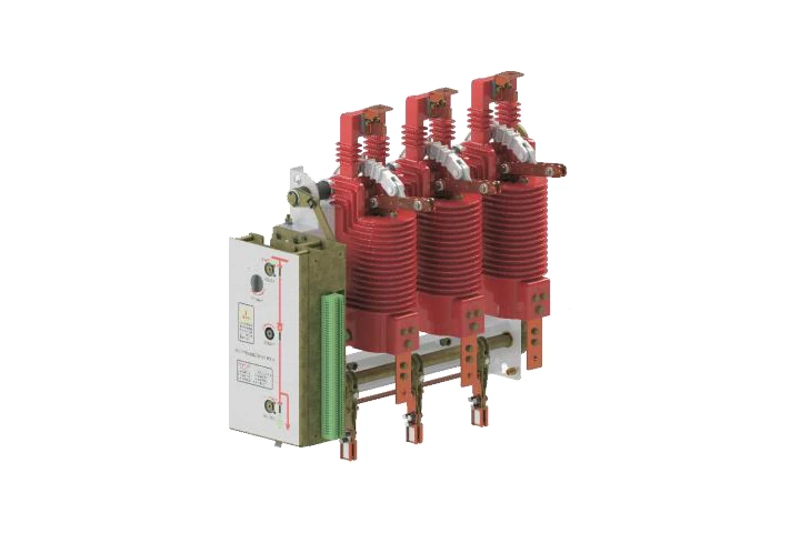
FZN64-12GD/630-25 load switch with its three-pole assembly and side operating mechanism.
Illustrated FZN64-12GD/630-25 arrangement. Confirm the selected model and cabinet fit against the approved order drawing.

An indoor AC vacuum load break switch for 12 kV, 50 Hz distribution cabinets. Specify the earthing arrangement, mounting direction, operating side and control method for your order.

Rated voltage
12 kV
Rated frequency
50 Hz
Rated current
630 A
Load-switch short-time withstand
20 kA / 4 s or 25 kA / 4 s
Mechanical endurance
10,000 operations

Key ratings are for the 630 A arrangement with an earthing switch. Confirm the exact G/GD order code and ratings for a 1250 A or non-earthing assembly. FZRN64 is a separate switch-fuse combination.

FZN64 technical specifications.

Electrical and mechanical ratings for the 630 A arrangement with an earthing switch. Confirm the exact G/GD order code, short-time withstand option and control supply before specifying the assembly.

Electrical ratings — 630 A earthing-switch arrangement
No.ItemUnitValue
01Rated voltagekV12
02Rated frequencyHz50
03Rated currentA630
04Fuse rated short-circuit breaking currentkA—
05Rated breaking transfer currentA—
06Rated active-load breaking currentA630
07Rated 5% active-load breaking currentA31.5
08Rated closed-loop breaking currentA630
09Rated cable-charging breaking currentA10
10Rated line-charging breaking currentA1
11Rated earth-fault breaking currentA30
12Rated cable-charging breaking current under earth-fault conditionsA17.4; 21.7
13Rated no-load transformer breaking capacitykVA2000
14Rated single capacitor-bank breaking currentA400
15Rated short-time withstand currentkA / sLoad switch incl. isolator: 20/4 and 25/4; earthing switch: 20/2 and 25/2
16Rated short-circuit making currentkA50; 63
17Rated peak withstand currentkA50; 63
18Power-frequency withstand voltage, 1 min, phase-to-earth / phase-to-phase and across vacuum / isolating gapskV / kV42 / 48
19Lightning-impulse withstand voltage, full-wave peak, phase-to-earth / phase-to-phase and across vacuum / isolating gapskV / kV75 / 85

A dash means no applicable rating is specified for this load-switch arrangement. FZRN64 switch-fuse combination ratings are separate. Confirm the applicable earth-fault cable-charging, short-circuit making and peak withstand values on the approved rating schedule.

Mechanical and operating data

Mechanical and operating characteristics
No.ItemUnitValue
20Main-circuit resistanceµΩ≤90
21Mechanical enduranceoperations10000
22Contact opening distancemm8–10
23Contact overtravel (spring compression length)mm3–4
24Cumulative contact wear thicknessmm3
25Average opening speedm/s0.8–1.2
26Average closing speedm/s0.45–0.85
27Rated contact pressureN900 ± 200
28Closing bounce timems≤2
29Three-phase closing/opening asynchronismms≤1
30Phase-center distancemm210
31Clearance between live parts and to earthmm≥125
32Vacuum load-switch closing torqueN·m≤80
33Vacuum load-switch opening forceN≤10
34Rated closing operating voltageV220 / 110
35Rated opening operating voltageV220 / 110
36Fuse-striker time to trip the load switchms—
37Fuse-striker output energyJ—

Specify 110 V or 220 V AC or DC for the selected mechanism. Confirm its final operating circuit and contact requirements before ordering.

Service conditions

Normal service conditions
No.ItemUnitValue
01Altitudem≤ 1,000
02Ambient temperature°C−25 to +40
03Relative humidity, daily average%≤ 95
04Relative humidity, monthly average%≤ 90
05Atmosphere—No obvious pollution by corrosive or combustible gases or water vapour
06Fire or explosion hazard—No fire or explosion hazard
07Seismic intensitydegree≤ 8
08Inclination°≤ 5

Confirm ratings separately for a 1250 A or non-earthing assembly. Installations outside these service conditions require an agreed specification.

Mounting and control options.

Normal and inverted mounting are available. Match the earthing arrangement, cabinet dimensions, operating side and wiring to the approved order drawings.

Normal and inverted mounting

ArrangementMechanical and primary fitControl and interlocks
Normal installationSide-operated. Confirm mounting points, cable entry, primary clearances and the left- or right-hand operating side against the cabinet layout.When an earthing switch is fitted, its side must not be the incoming-line side. Confirm the selected mechanical and electrical interlocks.
Inverted installationSelect inverted mounting for bottom cable entry when an earthing switch is fitted. Check mounting points, clearances and operating-side access.Keep the earthing-switch side away from the incoming line. Confirm the interlocks and final wiring for the selected assembly.

For a 900 mm cabinet depth, the standard interface dimensions are 225 mm from the panel to the mounting hole and 525 mm from the panel to the B-phase centre. Confirm them on the approved order drawing; other dimensions must be specified.

Model and operating side
  • Model: FZN64-12G or FZN64-12GD, with 630 A or 1250 A and 20 kA or 25 kA short-time withstand options. Specify whether an earthing switch is required and confirm the complete order code.
  • Operating side: all arrangements are side-operated; specify left- or right-hand operation.
  • Rating scope: the detailed values on this page cover the 630 A earthing arrangement. Confirm 1250 A or non-earthing ratings separately. FZRN64 is a separate switch-fuse combination.
Mechanism and control supply
  • Mechanism: manual, motor-operated, or manual closing with electric tripping. The manual version has no auxiliary contacts or wiring; manual closing with electric tripping accepts AC or DC control power.
  • Supply: specify 110 V or 220 V AC or DC. The standard supply is AC 220 V; AC and DC motor versions are not interchangeable.
  • Closing circuit: select closing self-hold if required. The standard circuit has no relay self-hold function.
  • Other options: live-voltage sensor, electromagnetic lock, back-to-back interlock, live-voltage indicator and program lock. The sensor is omitted as standard.

Auxiliary contacts and microswitches

CircuitStandard reservation
Auxiliary switch2 NO + 2 NC
Isolator microswitch1 NO + 1 NC
Earthing-switch microswitch1 NO + 1 NC

NO = normally open; NC = normally closed. These reservations apply where auxiliary circuits are fitted. Confirm the final supplied contact set and terminal allocation; the manual version has no auxiliary contacts or wiring.

Mechanical interlock sequence

  1. Opening and earthing

    The load switch must be open before the isolator can open. The isolator must be open before the earthing switch can close.

  2. Returning to service

    The earthing switch must be open before the isolator can close. The isolator must be closed before the load switch can close.

  3. Cabinet-door interlocks

    The earthing switch must be closed before the cabinet door can open. The door must be closed before the earthing switch can open.

Confirm the interlock sequence for the selected assembly and cabinet-door arrangement.

FZN64 installation drawings.

Check the 630 A outline and compare mounting orientations with your cabinet layout. Confirm the selected model, mounting points, operating-side access and final dimensions before installation.

Choose a drawing reference

630 A outline and panel interface

Open full-size drawing
FZN64-12D/630 front and side dimensions for the normal left-hand operating arrangement.

Use the front and side views to check mounting holes, phase spacing and cabinet clearances. Dimensions are in mm. The door cutout is 210 × 424 mm; mechanism dimension L is normally 200 mm and may be customized.

The illustrated FZN64-12D/630 arrangement is a dimensional reference. Confirm all installation dimensions on the approved order drawing.

Open full drawing at PDF page 3

Normal and inverted mounting

Open full-size drawing
FZN64 normal and inverted side-mounted arrangements with left- and right-hand operation.

Compare the four side-mounted arrangements: normal left-hand operation, normal right-hand operation, inverted left-hand operation and inverted right-hand operation. Confirm the required orientation and operating side for the cabinet.

The illustrated FZN64-12D/630 arrangement is a dimensional reference. Confirm all installation dimensions on the approved order drawing.

Open full drawing at PDF page 3

FZN64 manual and selection form.

The manual provides ratings and installation guidance. Use the selection form to specify the switch and operating options for your order.

Available · PDF · 5 pages

FZN64 / FZRN64 product manual

Model codes, ratings, operation, outline dimensions and mounting arrangements. Match the FZN64 load-switch or separate FZRN64 switch-fuse configuration before use; the detailed FZN64 ratings cover the 630 A arrangement.

Open manual PDF

Available · DOC · 2 pages

FZN64 / FZRN64 selection form

Specify the model, earthing option, mounting arrangement, operating side, mechanism, control supply, cabinet interface, auxiliary contacts and interlocks. Select the correct FZN or FZRN product prefix.

Download selection form

Price & quotation.

Configuration · FZN64-12 630 A

FZN64-12 630 A vacuum load switch

Liqiang reference quotation for a 12 kV, 630 A non-fuse vacuum load-switch assembly with isolation, earthing and a basic spring mechanism. Confirm the selected mechanism and cabinet interfaces before ordering.

Rated voltage
12 kV
Rated current
630 A
Quoted scope
Non-fuse switch assembly

Liqiang reference price

USD 750–1500 / set

USD per complete three-phase switch assembly. Final pricing is subject to the actual configuration, order quantity and written quotation from Liqiang. Cabinet, fuse equipment, optional motor/control package, shipping, taxes and installation are excluded.

This reference price range is provided by Liqiang for initial project enquiries. Request a written quotation to confirm the selected configuration and supply scope.

Quotation details

Request a written quotation from Liqiang

View configuration image

FZN64 selection questions.

Answers to common questions about ratings, mounting, controls and cabinet fit.

01Which ratings does the detailed table cover?

The detailed ratings apply to the 630 A earthing arrangement. Confirm the complete ratings separately for 1250 A or non-earthing assemblies. See the complete ratings and service conditions.

02How do FZN64 and FZRN64 differ?

FZN64 is the bare vacuum load switch. FZRN64 is a separate load-switch/fuse combination. Their ratings and drawings are not interchangeable; do not apply FZRN64 fuse-combination ratings to a bare FZN64 switch. See the technical documents for the selected model.

03Which mounting arrangement should I specify?

Specify normal or inverted mounting and left- or right-hand operation. When an earthing switch is fitted, its side must not be the incoming-line side; bottom cable entry requires inverted mounting. Confirm cabinet clearances and operating access in the mounting and control requirements.

04Can AC and DC motor versions be interchanged?

No. Specify 110 V or 220 V AC or DC; the standard control supply is AC 220 V. AC and DC motor versions are not interchangeable. Manual closing with electric tripping accepts AC or DC control power. Confirm the mechanism, supply and final wiring in the control requirements.

05Can I use the outline as the final cabinet drawing?

Use the FZN64-12D/630 figure as a reference. The door cutout is 210 × 424 mm and mechanism dimension L is normally 200 mm, with customized dimensions available. Final mounting points, clearances and cabinet fit must follow the approved order drawing. See the drawing references.

06What should I specify for an order?

Provide the complete model code, rated current and short-time withstand option, earthing requirement, mounting orientation, operating side, mechanism, control supply, cabinet depth, auxiliary contacts and interlocks. Specify the bare FZN64 switch or separate FZRN64 combination and include the cabinet drawing. Complete the selection form.

Product engineering series

About Liqiang

Manufacturing and technical support.

Technical selection guide