Choose a view to inspect the breaker and its contacts.

12 kV series · Indoor switchgear

VS1-12Indoor vacuum circuit breaker

For indoor medium-voltage switchgear. Match rated current and short-circuit duty to your panel requirements, then confirm the arrangement, cabinet interfaces and operating supply against the selected drawings.

Rated voltage
12 kV
Rated frequency
50 Hz
Rated current
630–4,000 A*
Breaking current
20 / 25 / 31.5 / 40 kA
Insulation level
42 kV / 1 min · 75 kV peak
Mechanical endurance
10,000 operations

*Rated-current options depend on the selected breaking-current variant. Confirm the exact combination and arrangement before ordering.

Model options

  • VS1(ZN63)-12 / 630-25
  • VS1(ZN63)-12 / 630-31.5
  • VS1(ZN63)-12 / 1250-25
  • VS1(ZN63)-12 / 1250-31.5
  • VS1(ZN63)-12 / 1250-40
  • VS1(ZN63)-12 / 1600-31.5
  • VS1(ZN63)-12 / 1600-40
  • VS1(ZN63)-12 / 2000-31.5
  • VS1(ZN63)-12 / 2000-40
  • VS1(ZN63)-12 / 2500-31.5
  • VS1(ZN63)-12 / 2500-40
See all 33 technical parameters

Technical specifications.

The complete specification table for VS1(ZN63)-12.

VS1(ZN63)-12 main specifications and technical parameters
No.ItemUnitValue
01Rated voltagekV12
02Rated short-duration power-frequency withstand voltage (1 min)kV42
03Rated lightning impulse withstand voltage (peak)kV75
04Rated frequencyHz50
05Rated currentA20 / 25 kA: 630, 1,250
31.5 kA: 630, 1,250, 1,600, 2,000, 2,500, 3,150
40 kA: 1,250, 1,600, 2,000, 2,500, 3,150, 4,000
06Rated short-circuit breaking currentkA20 / 25; 31.5; 40
07Rated short-time withstand currentkA20 / 25; 31.5; 40
08Rated short-circuit durations4
09Rated peak withstand currentkA20 / 25 kA: 50 / 63
31.5 kA: 80
40 kA: 100
10Rated short-circuit making currentkA20 / 25 kA: 50 / 63
31.5 kA: 80
40 kA: 100
11Secondary-circuit power-frequency withstand voltage (1 min)V2,000
12Rated single / back-to-back capacitor-bank breaking currentA630 / 400 (40 kA version: 800 / 400)
13Rated capacitor-bank switching inrush currentkA12.5 (frequency ≤ 100 Hz)
14Opening time at rated voltagems≤ 50
15Closing time at rated voltagems≤ 60
16Mechanical enduranceoperations10,000
17Rated-current interruption count (electrical life)operations10,000
18Rated short-circuit current interruption countoperations50 (40 kA version: ≤ 30)
19Permissible accumulated contact wear (moving / static)mm3
20Rated closing-coil voltageVAC 110 / 220; DC 110 / 220
21Rated tripping-coil voltageVAC 110 / 220; DC 110 / 220
22Spring-charging motor rated voltageVAC 110 / 220; DC 110 / 220
23Spring-charging motor rated powerW70
24Spring-charging times≤ 10
25Contact gapmm11 ± 1
26Contact overtravelmm3.5 ± 0.5
27Contact closing bouncems≤ 2 (40 kA version: ≤ 3)
28Three-phase closing / opening asynchronismms≤ 2
29Average opening speedm/s1.1 ± 0.2
30Average closing speedm/s0.6 ± 0.2
31Main-circuit resistance (fixed / withdrawable)μΩ630 A: ≤ 45 / ≤ 60
1,250 A: ≤ 40 / ≤ 55
1,600–2,000 A: ≤ 30 / ≤ 50
2,500 A and above: ≤ 25 / ≤ 35
32Contact closing pressureN20 kA: 2,000 ± 200
25 kA: 2,400 ± 200
31.5 kA: 3,100 ± 200
40 kA: 4,250 ± 250
33Rated operating sequenceO – 0.3 s – CO – 180 s – CO

Installation and control options.

Choose the arrangement first. Then check primary connections, interlocks, insulation construction and operating supply against your switchgear drawings.

Fixed, withdrawable and side-mounted arrangements
ArrangementMechanical and primary fitControl and interlocks
FixedMounting points, primary terminal positions, phase spacing and pole spacing.Top and main-shaft interlock directions, including any extension requirements.
WithdrawableCabinet width, carriage interface, primary contacts, phase spacing and pole spacing.Carriage interlocks and secondary connections.
Side-mountedOutline, cabinet interface and left- or right-hand outlet direction.Top and main-shaft interlock directions, including any extension requirements.
Insulation construction
Choose embedded poles or insulating cylinders. Confirm the structure for the selected arrangement and electrical duty.
Mechanism and operating supply
Specify spring or permanent-magnet operation, plus closing, tripping and spring-charging supply. Confirm auxiliary contacts and secondary-circuit details separately.

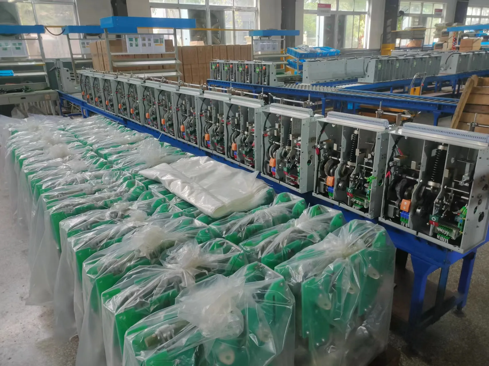
The workshop photograph is shown for general context, not as a VS1-12 installation or dimensional reference. Confirm the exact arrangement and interfaces against the drawings for your order.

VS1-12 · Technical references

Drawings and secondary circuits.

Fixed-arrangement outline and English secondary-circuit drawings for cabinet layout and control wiring.

Select a reference

Fixed-arrangement installation

Fixed VS1(ZN63)(800) outline

Open full page
Fixed-arrangement reference only.This drawing does not depict the withdrawable breaker shown in the product gallery.

Fixed-arrangement control circuits

Secondary-circuit references

Open original manual
For engineering reviewThese fixed-arrangement drawings help check circuit functions, control-supply options and terminal assignments. Confirm the final drawing against the ordered mechanism, optional devices and control voltage.
Select a circuit drawing

Internal circuit schematic · fixed arrangement

Open full-size English diagram
Fixed-arrangement VS1-12 internal circuit schematic with circuit groups, control-supply jumper options and component key.
Confirm jumper settings and fitted components against the approved order circuit drawing.For fixed arrangement only.

Internal wiring and terminal map · fixed arrangement

Open full-size English diagram
Fixed-arrangement VS1-12 internal wiring and terminal map with terminal numbers and component codes.
PCB key: V2 closing · V4 interlock · V1 spring charging · V3 trip.Confirm terminal assignments against the approved order wiring schedule.

Use these fixed-arrangement circuit references to coordinate the control interface. Confirm terminal assignments and polarity on the approved order wiring drawing before installation.

Original manual · PDF page 11

Need a different arrangement or control supply? Request drawings for your selected configuration.

Product manual and test report.

The type-test report is available on request for the named sample.

Cover of the VS1(ZN63)-12 product manual.

Available now

VS1 (ZN63)-12 product manual

Operation, structure, outline drawings and secondary-circuit references.

Open manual PDF

On request

VS1-12/1250-31.5 type-test report

Report 2113345384, dated 14 May 2021, lists 13 test categories for two VS1-12/1250-31.5 samples, including insulation, short-time and peak withstand, short-circuit interruption, electrical endurance, mechanical tests and temperature rise. Its coverage must be matched to the ordered rating, insulation construction and arrangement.

Request sample report

See Liqiang manufacturing and inspection activities. Model reports and factory inspection records serve different purposes; match the required documents to the proposed equipment.

Price & quotation.

Configuration · VS1(ZN63)-12/630-25

VS1(ZN63)-12/630-25 drawout indoor vacuum circuit breaker

Price reference for the specified VS1(ZN63)-12/630-25 configuration. Drawout arrangement; fixed and side-mounted versions are quoted separately.

Rated voltage
12 kV
Rated current
630 A
Short-circuit breaking current
25 kA
Arrangement
Drawout

Price range

USD 885–895 / set

USD per complete three-phase set. Minimum order: 1 set. USD 895 per set for 1–19 sets; USD 885 per set for 20+ sets. Shipping and taxes are excluded. Other configurations and accessories require a separate quotation. Confirm the specification and final quotation before ordering.

The range reflects order-quantity tiers for this configuration; it does not cover every option in the series.

Quantity pricing
Published quantity tiers for this configuration
Quantity (sets)Price per set
1–19USD 895
20+USD 885

VS1-12 · Product selection

Frequently asked questions.

Quick answers on rating combinations, installation fit and product documentation.

01Which rated-current and short-circuit combinations are listed?

Options depend on breaking duty: 20/25 kA — 630 or 1,250 A; 31.5 kA — 630, 1,250, 1,600, 2,000, 2,500 or 3,150 A; 40 kA — 1,250, 1,600, 2,000, 2,500, 3,150 or 4,000 A. Check the complete specification table for the exact combinations.

02Which installation arrangements can be specified?

Specify fixed, withdrawable or side-mounted construction. Confirm mounting points, cabinet dimensions, primary connections and interlocks against the requirements for your selected arrangement in the configuration section.

03What operating-supply options are listed?

The specification table lists AC 110/220 V and DC 110/220 V options for the closing coil, tripping coil and spring-charging motor. Confirm the required supply and mechanism for your configuration.

04How should I specify the VS1-12 secondary control circuit?

Specify the supply for the closing coil, tripping coil and spring-charging motor, together with auxiliary-contact and interlock requirements. For replacement equipment, include the existing terminal schedule and connector details. Use the secondary-circuit drawings to discuss the arrangement, then match the final wiring diagram to the selected breaker.

05How do I choose between embedded poles and insulating cylinders?

Embedded poles enclose the vacuum interrupter in solid insulation; an insulating-cylinder design uses a separate insulating enclosure around the interrupter assembly. For VS1-12, compare the required insulation level, site conditions, cabinet space and maintenance access, then specify the construction with the mounting arrangement and electrical duty. See the insulation and installation options.

06What information should I send with an inquiry?

For a new panel, prepare the cabinet outline, primary-connection drawing and control schematic. For a replacement, include the nameplate, photos, dimensions and interfaces to match. Also specify the required duty, arrangement, operating supply, quantity and destination.

Product engineering series

About Liqiang

Manufacturing and technical support.

Technical selection guide