Indoor VCB Installation Dimensions: Pole Spacing, Contact Height and Cabinet Fit
Approx. 15 min read
Quick Takeaway
Identify the exact breaker and cabinet configuration and their applicable drawing revisions before comparing interfaces; a nominal cabinet width does not establish fit.
Compare adjacent pole centres, both primary-contact heights and fore-aft engagement against agreed datums and approved limits. Matching upper-to-lower spacing alone does not establish absolute height.
Record each interface as agreed, mismatched or unresolved, with its drawing pair, values, limits and action owner. Accept dimensional compatibility only for the named ordered assembly.
Identify the exact assembly before comparing dimensions
The first task before comparing any dimensions is to identify the exact assembly you are working with. A breaker and a retained cabinet each need their own specification: arrangement (fixed, side-mounted, or withdrawable/handcart), full designation, selected current rating and primary-contact option, and the drawing revision that governs that configuration.
For the three models in scope — VS1-12, VS1-24 and ZN85-40.5 — the installation and cabinet-matching drawings are arranged differently. The VS1-12 manual separately presents handcart, fixed and side-mounted outlines, each with its own front and side views. The handcart outline carries cabinet-width variants and a table linking rated-current and duty rows to matching contact sizes. Fixed versions use separate base-hole and outline drawings. The side-mounted outline identifies right outgoing connections and left interlock, and notes that selected dimensions may be made to user requirements. None of these can be combined into one VS1-12 dimension set.
The VS1-24 manual similarly separates handcart and fixed outlines, with the front view locating phase centerlines and the side view locating terminal and contact heights relative to the shown frame or chassis. Its recommended cabinet-matching section is a separate drawing from the breaker envelope, and its current and duty table selects matching contact sizes.
The ZN85-40.5 drawings cover sealed-pole handcart configurations. Two named outline drawings show front and side views with upper and lower primary contacts relative to a chassis base, with separate dimension lines for vertical contact separation, fore-aft projection and wheel/frame positions. Their front-view phase spacing, outside widths and selected contact and duty coverage differ between the two drawings, so their dimensions cannot be combined.
A catalogue overall width or a cabinet nominal width does not identify the mating interface. Two breakers can share a nominal cabinet width but differ in pole-centre spacing, contact height above the mounting datum, or the depth at which the moving contact reaches the fixed contact in the cabinet. Product photographs and family designations are not order-specific installation drawings. The VS1-12, VS1-24 and ZN85-40.5 product pages each present several scoped outline and contact-interface options rather than one dimension for every unit, and their galleries do not necessarily depict the same arrangement.
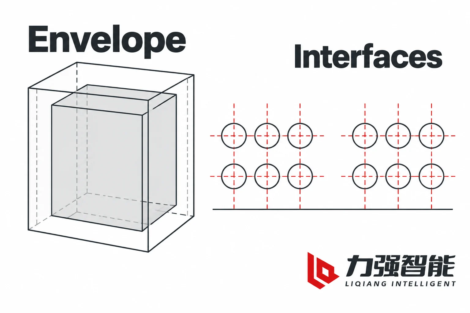
Overall envelope and interface coordinates answer different fit questions. Abstract concepts; no product dimensions are supplied.
Separate pole spacing, contact height and contact reach
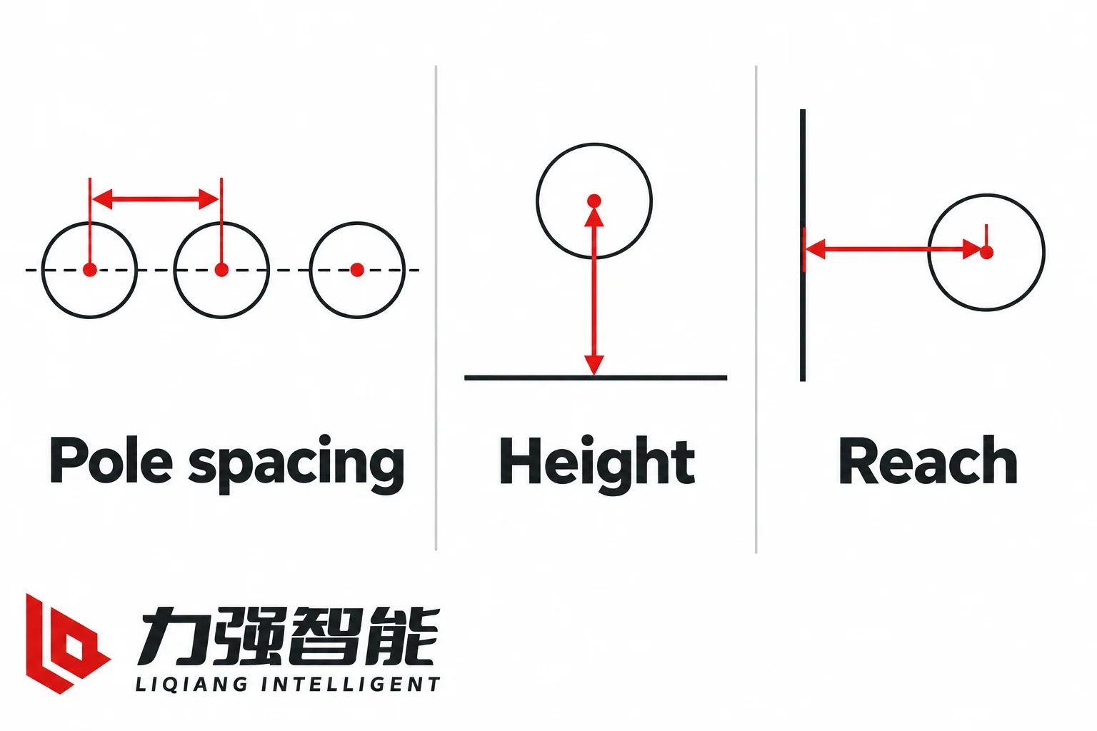
Three distinct dimensional relationships govern how a breaker mates with a cabinet. Understanding these as separate axes — rather than a single “does it fit?” question — is what makes a dimensional review useful.
Pole-centre spacing is the transverse distance between phase centerlines, measured across the three poles in the front view. It helps determine whether the breaker’s primary-contact axes align with the cabinet’s corresponding fixed-contact axes phase by phase. If the primary-contact axes fall outside the approved alignment limits, the moving and fixed interfaces may fail to engage correctly even when the outer envelope fits.
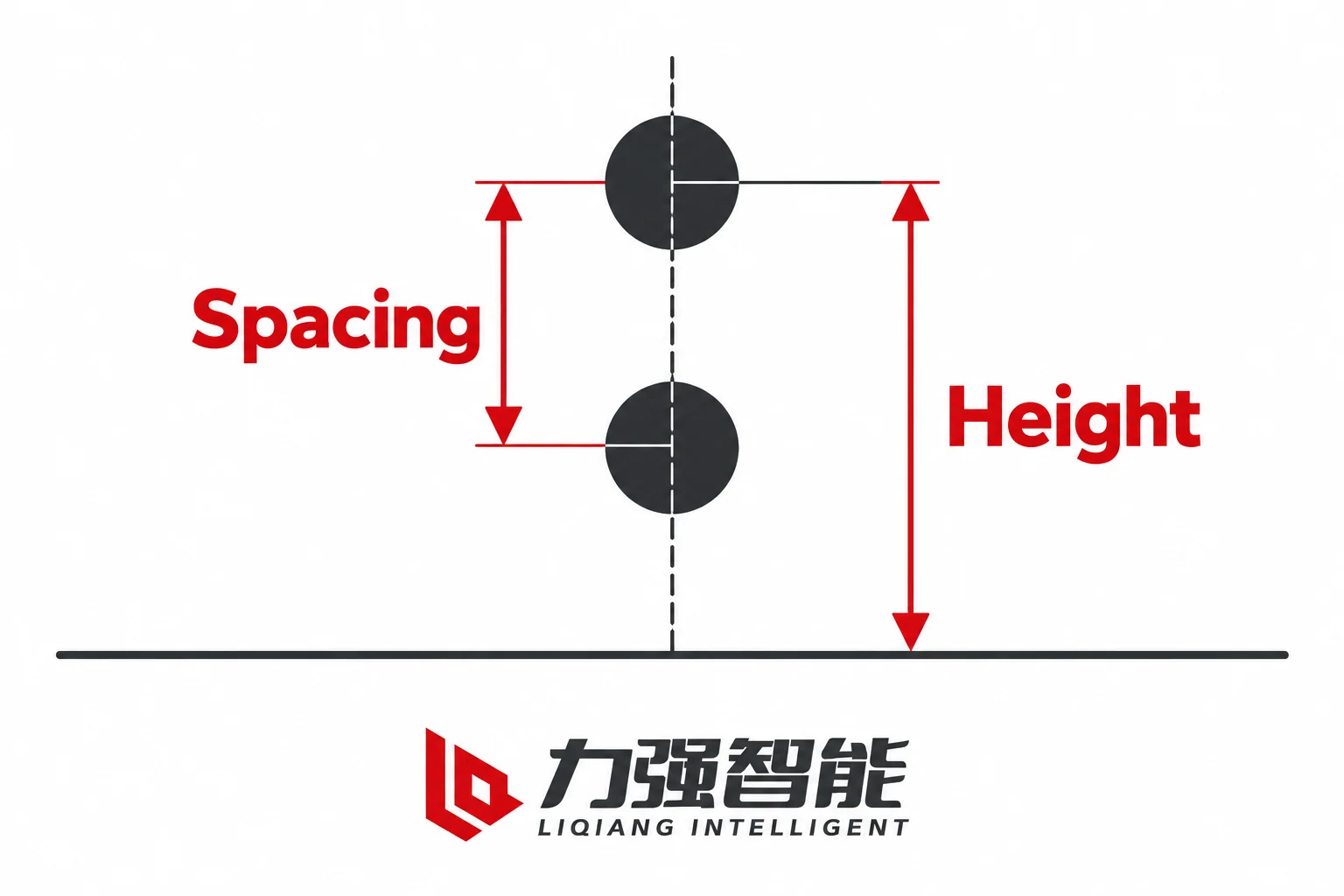
Contact height is the absolute vertical position of the upper and lower primary contacts measured from an agreed datum — a mounting plane for fixed breakers, or a carriage rail level for withdrawable breakers. The upper-to-lower relative spacing (the distance between the upper and lower contact centerlines) can match between breaker and cabinet while both contacts sit at the wrong absolute height. A retained-cabinet comparison can therefore show this condition: even when the contacts are already parallel and correctly oriented, a matching upper-to-lower spacing can coexist with a vertical offset of the whole pair relative to the cabinet’s fixed contacts.
For a withdrawable arrangement, contact reach describes the fore-aft position of the moving primary interface relative to the cabinet fixed contact and the agreed travel reference. A fixed arrangement instead requires the primary terminal or connection coordinates to be reconciled with its mating connection. In a withdrawable breaker, this involves the carriage travel from the test/disconnected position to the service position, the shutter opening sequence, and the overlap or engagement distance between moving and fixed contacts. The ZN85-40.5 drawings separately identify the insertion mechanism total travel, which means an overall contact height does not establish where the chassis stops or how the contacts engage.
These three axes are independent. A breaker can match pole centres and still miss on height. It can match height and still have insufficient reach. The approved contact geometry and tolerances — not the overall outline — determine whether engagement is correct. You cannot infer insertion depth, compression or permissible engagement from an external envelope drawing, and no universal dimensions apply across models or arrangements.
Pole spacing, contact height and reach use different reference relationships. These unnumbered concepts supply no installation values.
Compare the breaker and cabinet from the same datums
A dimensional comparison is only valid when both drawings use the same reference system. Align the corresponding axes and views (front, side or top), relate the dimensions to a common reference plane or datum, and express them in agreed units. Identify the applicable revision of each drawing; the breaker and cabinet do not need identical revision labels. A cabinet floor and a carriage rail are different datums: comparing a breaker contact height measured from the chassis base against a cabinet fixed-contact height measured from the compartment floor will produce a misleading offset even if both numbers are individually correct.
For fixed mounting, the comparison covers the base-hole pattern, the support plane, and the primary-connection coordinates. The breaker’s mounting holes must align with the cabinet’s support structure, and the primary terminal positions must match the bushing or bus-bar interface in the cabinet.
For withdrawable (handcart) mounting, the comparison is more involved. Beyond the basic mounting, you need to check:
Carriage or rail level: the height at which the breaker chassis rolls into the cabinet
Guide relationship: whether the guides in the cabinet steer the breaker into the correct lateral position
Travel positions: the distances from test/disconnected to service position, and whether the full travel brings the contacts into engagement
Fixed contacts: the position and geometry of the stationary contacts in the cabinet
Shutters: whether the selected shutter arrangement clears and covers the primary openings at the positions required by the approved cabinet design
Interlock interface: whether the mechanical and electrical interlocks engage at the right positions in the travel sequence
The VS1-12 recommended breaker-to-cabinet sections depict the moving contact against the retained fixed contact and insulating bushing, with a depth and engagement relationship in addition to vertical centreline spacing. The VS1-24 moving and fixed-contact detail depicts the engagement relationship. These are interface checks, not overall-size checks.
Tolerances and cumulative alignment require the responsible assembly design. Every dimensional comparison carries manufacturing and assembly tolerances on both sides — the breaker and the cabinet — and the combined effect can push a nominally matching interface out of engagement. Obtain the applicable interface limits and tolerance assessment from the responsible assembly design records; resolve any missing limit before accepting the fit. Do not use unapproved field modifications, such as elongating holes, bending contact arms or adapting primary contacts, to resolve a dimensional mismatch. Any proposed engineered change requires approval against the assembly design and its relevant mechanical and insulation requirements before implementation.
Relative contact spacing and absolute height from a datum are different measurements. Confirm both against the applicable drawings.
Check the complete installation envelope and moving interfaces
The static outer envelope — the bounding box the breaker occupies when installed — is necessary but not sufficient for cabinet fit. After the outer outline clears, several additional conditions remain.
Mating coordinates are the specific points where the breaker’s contacts, secondary connector and interlocks meet the cabinet’s corresponding interfaces. A breaker can fit inside the cabinet envelope while its contacts are displaced from the fixed contacts. The VS1-24 product page presents several scoped outline and contact-interface options rather than one dimension for every unit, which is why selection depends on the exact arrangement, current configuration, pole centres, upper and lower contact interface, mounting or carriage and cabinet matching.
Movement and access conditions include:
Front controls and secondary reach: the operating mechanism, position indicator and secondary-plug location need accessible operating space
Door and shutter relationship: confirm the positions, clearances and interlock relationships required by the selected cabinet design
Racking and withdrawal movement: the breaker must travel its full distance without obstruction from bus bars, insulation barriers or compartment walls
Terminal and tool access: allow the access required for the selected primary and secondary connections, fasteners and inspection points
These are configuration-specific checks. A side-mounted VS1-12 arrangement, for example, has different protrusion and access requirements than a handcart version because the outgoing connections and interlock are on different sides. The VS1-12 side-mounted outline explicitly identifies right outgoing connections and left interlock, which creates different clearance needs than the handcart arrangement.
Dimensional fit alone does not establish insulation clearances or the electrical performance of a changed assembly. A breaker that physically fits a retained cabinet may still have insufficient creepage and clearance distances once installed, or the combined breaker-cabinet assembly may not meet the insulation level or short-circuit withstand it was originally designed for. Approved design governs these conditions; geometric fit is one input among several.
For projects that involve removing an existing breaker and taking it to the workshop, the room-to-workshop removal route — aisle widths, door openings, lifting access and transport clearances — belongs to the maintenance-space planning article on fixed versus withdrawable vacuum circuit breakers. That route plan is a separate check from the in-cabinet dimensional compatibility reviewed here.
Check static size, movement and access separately for the selected assembly. No clearance or operating sequence is specified.
Turn the drawings into a dimensional review record
A comparison table makes the dimensional review traceable and exposes gaps before they become field problems. Use the template below to record the applicable drawings and their interface values. Mark a missing value, datum or limit as unresolved and assign a specific enquiry. Where drawings start from different references, record the confirmed offset used to express both coordinates against the agreed datum.
Interface / axis
Agreed datum or reference
Cabinet: drawing / revision and required coordinate
Breaker: drawing / revision and proposed coordinate
Approved limits / tolerance
Status / action owner
A–B and B–C pole centres / transverse
Identified primary-contact axes
___
___
___
___
Upper primary-contact height / vertical
Common support or rail reference, with confirmed offsets
___
___
___
___
Lower primary-contact height / vertical
The same agreed height reference
___
___
___
___
Upper-to-lower contact separation / vertical
Corresponding contact centrelines
___
___
___
___
Primary reach and engagement / fore-aft
Identified interface and travel reference
___
___
___
___
Fixed mounting pattern and support
Agreed mounting planes and hole datums
___
___
___
___
Withdrawable carriage, rail and guides
Identified rail and lateral references
___
___
___
___
Travel, shutter and interlock interfaces
Selected assembly position references
___
___
___
___
Secondary assembly location and reach
Identified connector and harness reference
___
___
___
___
Static envelope, movement and access
Cabinet boundaries and moving parts
___
___
___
___
To see how this record works in practice, consider a conditional retained-cabinet project. A panel builder has a switchgear compartment with a nominal cabinet width and documented pole centres. The replacement breaker’s catalogue lists the same nominal width and the same pole-centre spacing. At first glance, the breaker appears to fit. But the cabinet drawing shows the fixed contacts at a specific height above the compartment floor, and the breaker drawing shows its moving contacts at a height above the carriage rail. If the carriage rail in this cabinet sits at a different level from the one the breaker drawing assumes — or if the contact reach differs because the fixed-contact bushing is a different form — the resulting interface could fall outside the approved alignment or engagement limits even though the nominal widths and pole-centre spacing match.
In this scenario, the direct-fit conclusion remains open. The precise drawing question that resolves it is: “What is the vertical distance from the carriage rail top surface to the centreline of the upper fixed contact in the cabinet, and what is the vertical distance from the breaker’s carriage rail interface to the centreline of the upper moving contact, using the applicable identified revision of each drawing?” Agreement within the approved limits confirms that upper-contact height coordinate. Check the lower-contact height and fore-aft engagement separately before closing the complete primary interface. A coordinate outside its approved limits is a documented mismatch requiring an approved design solution.
A second condition distinguishes a missing datum from a measured mismatch. If the cabinet drawing does not declare its datum — for example, it dimensions the fixed contacts from an unspecified reference — the status is “unknown” rather than “mismatch.” A documented dimensional mismatch means the compared values are expressed against identified common references and fall outside the approved interface limits. A missing datum means the comparison cannot be completed until the datum is confirmed. These two outcomes lead to different actions: a mismatch requires a design solution, while a missing datum requires a drawing enquiry.
Agreement, a documented mismatch and missing information lead to different review actions. The symbols describe record status.
Order the selected configuration against reconciled interfaces
Once the dimensional review is complete, the outcomes fall into three categories:
Interfaces agree within approved limits for the named assembly. The breaker and cabinet drawings, at their identified revisions, show mating interfaces that match within the tolerances specified by the responsible assembly design. The compatibility conclusion is bound to this exact ordered breaker and cabinet and drawing pair — not to all units of the same series. A subsequent order with a different current rating, contact option or arrangement must be rechecked.
Documented mismatch needs an approved design solution. Where a dimensional comparison shows that an interface does not agree within approved limits, resolve the mismatch through the responsible design process; an unapproved field modification is not an accepted resolution. This may involve selecting a different contact option, adjusting the cabinet interface under an approved design change, or choosing a different breaker configuration. The resolution is recorded against the specific interface and drawing pair.
Missing inputs remain unresolved. Where a drawing does not provide a datum, a value or a tolerance, the comparison cannot be completed. These items stay open until the drawing enquiry returns the missing information. An unknown is not an assumed match; it is an open item that blocks release until resolved.
The release boundary is the exact ordered breaker and cabinet configuration with their drawing revisions. A dimensional compatibility conclusion does not transfer to other units of the same series, other arrangements within the same model, or other current and contact options.
Dimensional enquiry package
Before quoting or ordering, assemble the following:
Breaker: full designation, arrangement (fixed, side-mounted or withdrawable), selected current rating and primary-contact option, drawing number and revision
Cabinet: retained cabinet identification, arrangement, nominal width, fixed-contact and bushing interface, drawing number and revision
Datums: the reference plane or datum used for each dimensional comparison, confirmed on both drawings
Comparison record: the completed table above with values, tolerances and status for each interface item
Open items: any interfaces marked unknown, with the specific drawing question that will resolve each one
Next steps and related reading
Submit the completed dimensional review and any open interface questions through the contact page.
For VS1-12 configuration references and enquiries, see the VS1-12 product page.
For VS1-24 configuration references and enquiries, see the VS1-24 product page.
Can I confirm cabinet fit by matching the breaker’s catalogue overall width to the cabinet’s nominal width?
No. Catalogue overall width and cabinet nominal width describe outer boundaries, not mating interfaces. Two breakers can share a nominal cabinet width while differing in pole-centre spacing, contact height above the mounting or carriage datum, and contact reach into the cabinet. The VS1-12, VS1-24 and ZN85-40.5 manuals each present arrangement-specific drawings with separate front and side views, and none of them reduces to a single width dimension for compatibility. An adequate outer-width envelope is one check among several; it does not establish that the primary contacts, carriage or rail level, shutter and interlock interfaces align. The dimensional review record compares each mating interface against a shared datum, which is what determines fit.
Why can the upper-to-lower contact spacing match and still leave the contacts misaligned?
Upper-to-lower relative spacing is the distance between the upper and lower primary-contact centerlines on the breaker, compared with the same distance on the cabinet’s fixed contacts. This relative dimension can match exactly while both contact pairs sit at the wrong absolute height — that is, at the wrong position above the declared datum. Imagine two contact pairs that are parallel and correctly spaced vertically, but one pair is displaced upward relative to the other. The contacts face the right direction and the gap between upper and lower is correct, but the moving contacts will meet air instead of the fixed contacts when the breaker is racked in. This is why contact height must be checked from a shared datum, not just as a relative spacing between upper and lower.
What should I do if the cabinet drawing does not declare its reference datum?
Treat the interface status as unknown, not as an assumed match. A missing datum means the comparison cannot be completed — you cannot determine whether the values agree because the cabinet drawing does not state where its dimensions are measured from. The correct next step is to raise a drawing enquiry asking for the specific datum (for example, carriage rail top surface, compartment floor or front frame) and the contact dimensions referenced to that datum. This is different from a measured mismatch, where the values have been compared against common identified references and fall outside the approved interface limits. A mismatch needs a design solution; a missing datum needs a drawing enquiry to close the gap.
Does a breaker that physically fits the cabinet envelope also meet the insulation and electrical requirements?
Not necessarily. An outer-envelope check confirms only that the stated outline clears the compared boundaries. It does not by itself establish mating-interface alignment, insulation clearances, creepage distances or the electrical performance of the combined assembly. A breaker that physically fits a retained cabinet may have different insulation barriers, bus-bar clearances or short-circuit withstand characteristics than the original assembly. These conditions are governed by the approved assembly design, which specifies the insulation level, clearance and creepage requirements for the specific configuration. Geometric fit is one input to that design judgment, not a substitute for it.
How is a dimensional compatibility conclusion bound to a specific order?
The conclusion applies only to the exact ordered breaker configuration (full designation, arrangement, selected current rating and primary-contact option, drawing revision) and the exact retained cabinet (identification, arrangement, drawing revision). It does not transfer to other units of the same series, other arrangements within the same model, or other current and contact options. If a subsequent order changes any of these — for example, selecting a different contact size or a different cabinet-width variant — the dimensional review must be repeated with the drawings for that configuration. This is why the release boundary is the ordered assembly and drawing pair, not the model family.
Share your love
William Xiaonan Liu
William Xiaonan Liu writes for LIQELE about medium-voltage switching equipment, including vacuum circuit breakers, load break switches, disconnectors and earthing switches. His articles explain product selection, installation interfaces, operating requirements and technical documentation, helping switchgear builders and project buyers identify the information needed for equipment selection and supplier discussions.