Switching and Protection in Medium-Voltage Feeders: Circuit Breakers and Switch-Fuse Combinations
Approx. 18 min read
Quick Takeaway
Normal switching changes a circuit connection on purpose; protection responds to an assigned abnormal condition. They may use the same contacts and mechanism, but opening alone does not establish current clearing, isolation or earthing.
Compare complete arrangements. Relay-based protection needs suitable current information, configured logic, a working trip-energy path and a breaker with the assigned interruption capability. A switch-fuse combination needs specified compatible links, striker and common-opening arrangements, with duties assigned to both switch and fuse.
Coordination compares actual response characteristics, current ranges and topology on a common reference. It must accommodate transformer energization while covering damaging events, preserve the intended branch selectivity, and respect assigned own-zone, backup and equipment withstand limits.
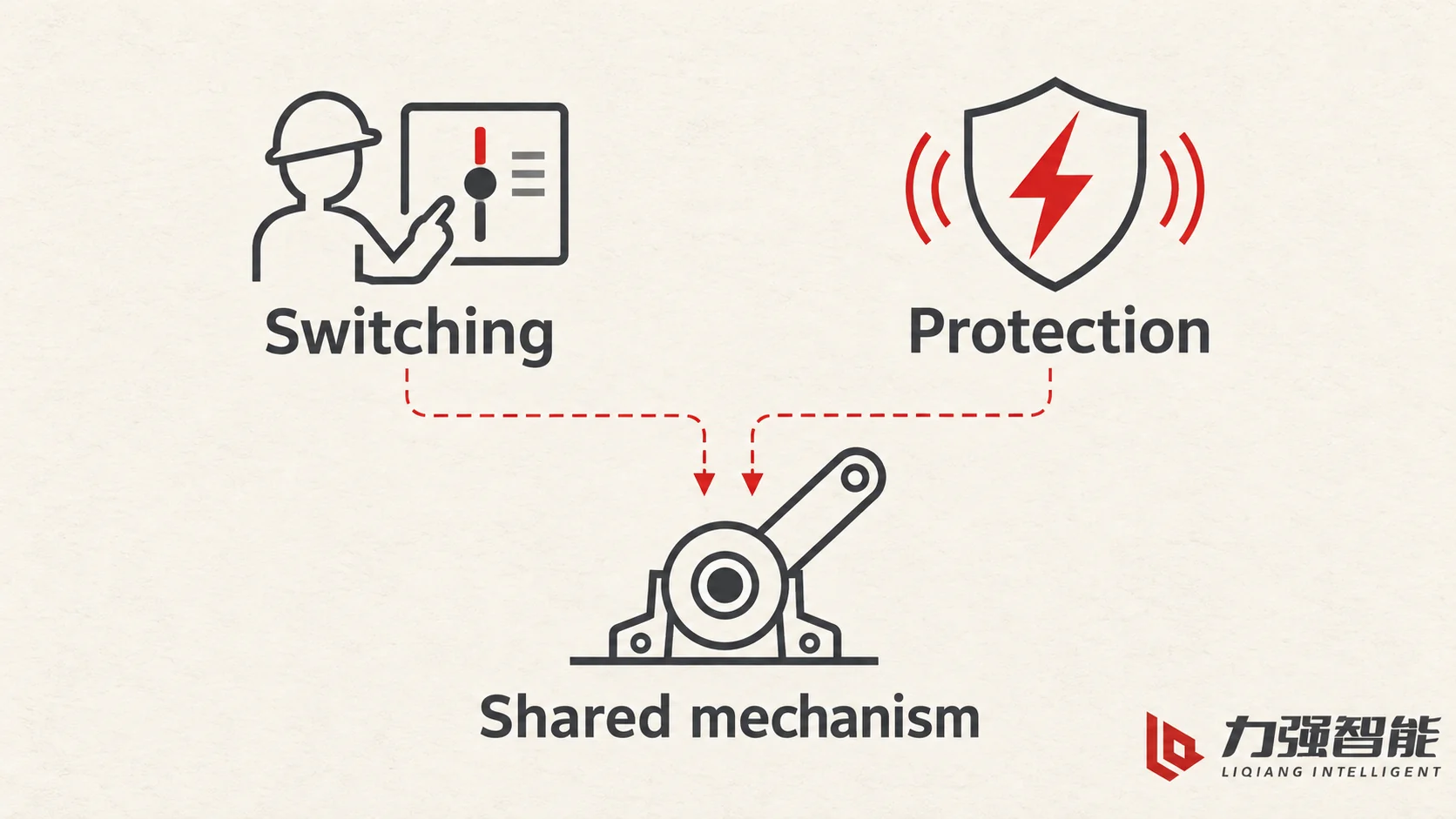
A medium-voltage feeder opens for two different reasons, and the difference matters more than the hardware on the panel. Normal switching changes the connected state of a circuit on purpose: transfer load, reconfigure a ring, sectionalise a healthy feeder before maintenance. Protection opens the circuit because an assigned abnormal condition was detected, and the opening is meant to interrupt current the circuit can no longer be allowed to carry. Both can end with the same contacts parting, and on many designs one operating mechanism carries out either command, but the information that starts the action, the electrical duty at the moment of opening and the consequence of getting it wrong are not the same.
The comparison is therefore between two complete arrangements, not two product names. On one side stands a measured chain: instrument transformers or sensors produce secondary information, a relay evaluates it against configured functions, a trip path with a suitable control supply reaches a release, a stored-energy mechanism moves the contacts, and a circuit breaker clears its assigned duty at the interrupter. On the other side stands a coordinated chain inside a documented switch-fuse combination: the fuse element responds to its own current and interrupts within its assigned range, a specified striker releases a common three-pole switch mechanism, and the switch poles then deal with the remaining switching and interrupting duties the combination assigns to them.
Neither chain can be compressed into a single component. The breaker’s interruption capability alone does not establish that the measurement, protection decision and trip path have been provided, and putting a fuse near a load switch does not by itself create a coordinated combination with a defined fault duty.
Intentional switching and protective response can use the same mechanism while their initiating information and electrical duties differ.
Switching duties and protective duties share hardware, not purpose
Normal switching uses the assigned switching duties: closing onto and opening from load current, often many times over the life of the installation, under the conditions the device was selected for. Protective opening is a response to an assigned abnormal condition, at a current the device must be able to interrupt within its assigned duty. A vacuum interrupter in a breaker does the second job and can also do the first, which is why the same mechanism serves manual, remote and protective commands. A load-break switch does the first job with its own assigned switching duty; that duty does not automatically include interrupting fault current, and a fuse’s fault capability does not include switching load.
Physical parts often carry several responsibilities at once. A shaft transfers motion and also defines the mechanical relationship between the three poles; a frame locates the poles and supports the mechanism; an auxiliary contact reports position and can also be part of a control or trip circuit. Recognising that overlap prevents a common error: reading a capability from one part and applying it to the whole assembly. It also prevents the opposite error, assuming that because a device can open, it can clear whatever current happens to be flowing. Mechanical opening is not current clearing, and a completed opening — by switch, by fuse or by breaker trip — is not by itself isolation or earthing of the installation, which remain separately documented functions.
The breaker feeder: from current information to interruption
The breaker arrangement is a causal chain, and each stage has its own failure mode.
Primary circuit information becomes secondary input. Current transformers, and voltage transformers where the configured functions need voltage, reproduce the primary quantities at a level the protection equipment can use. This is an information task, not a protection decision. What the information has to be good at depends on the job: metering accuracy is about following normal load quantities faithfully, while protection also has to follow rapidly changing quantities during a fault or disturbance, where the waveform is distorted and offset. A transformer ratio on its own therefore does not establish that the information suits a particular protection function, and an accurate metering reading does not establish that the same channel can follow a fault.
The relay evaluates and decides. The protection device applies its configured functions to the input and produces an output when the condition it watches for is met. Which quantities it needs — current only, or current and voltage — follows from the functions actually configured for that feeder, not from a general rule about medium-voltage schemes. Two housings or one integrated device changes nothing about the responsibility: logic is logic, and it does not clear current.
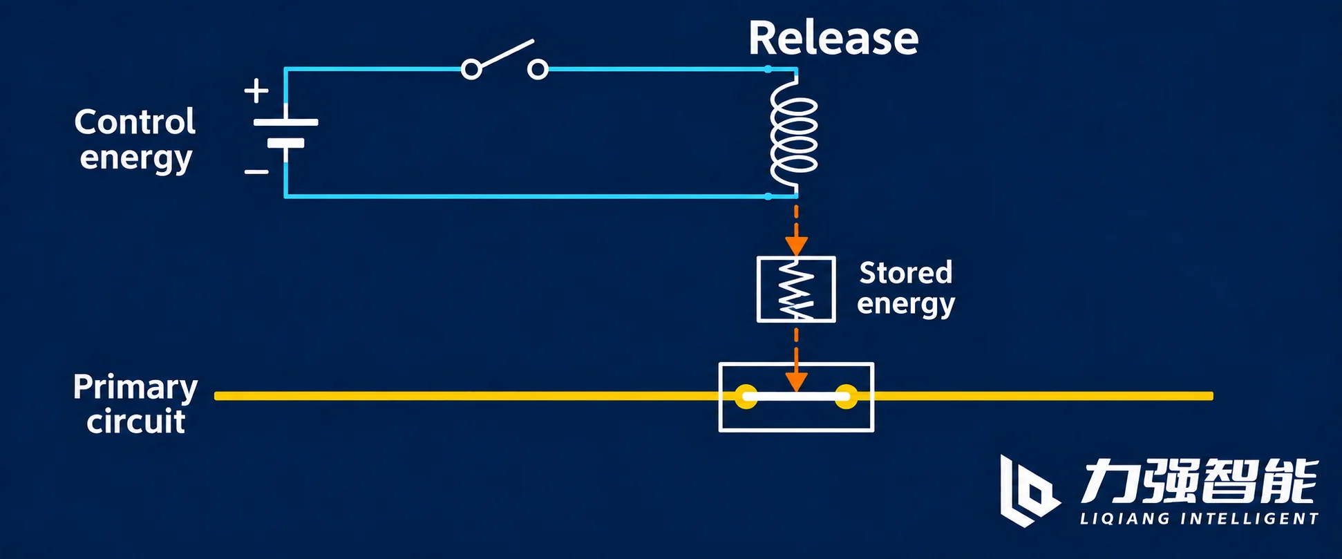
The trip command needs a path and energy. The relay output has to reach a release that can act on the mechanism: a shunt-trip coil, or an alternative actuator arrangement where that is what the selected operating principle uses. The selected release needs its specified trip energy at the moment it must act. An externally supplied shunt-trip circuit depends on that control supply and circuit; other arrangements may use a different actuator or energy source. The trip command and its actuation energy remain distinct from the fault current the breaker interrupts.
Stored mechanical energy moves the contacts. The mechanism holds energy — typically in springs held charged while the breaker is closed — and that stored energy drives the main contacts apart. It is mechanical energy, made available at the moment of release, not a share of the fault current.
The interrupter clears its assigned duty. The contacts part and the interrupter extinguishes the arc and completes the interruption within the breaking capability of the breaker as applied. The breaker structure and the interruption principle themselves are a separate subject; the vacuum circuit breaker explanation covers that anatomy, and this section only needs the place it occupies in the chain.
Keeping these stages distinct explains two failure modes that look identical in a schematic. If the trip path is broken — no control supply, an open circuit, a mismatched release — the breaker simply does not operate, however capable it is. If the breaker is applied where the prospective fault current exceeds its assigned breaking capability, the protection may operate correctly and the breaker still fail to clear. A relay cannot increase breaking capability; a generous breaker rating cannot establish that sensing, logic and trip path were provided.
In this externally supplied shunt-trip example, the control loop actuates the release, stored mechanical energy moves the contacts, and the primary circuit remains a different electrical path.
The switch-fuse branch: two current duties inside one documented combination
In a switch-fuse combination the work is divided, and the division is what has to be examined.
The fuse handles its own part without needing a relay. Current through the element heats it; at sufficient current and duration the element melts, an arc forms across the gap, and the fuse’s interrupting construction extinguishes that arc. Within its assigned current-limiting range, the fuse interrupts before the unrestricted prospective fault current would reach its peak, so the actual peak the installation sees is lower than the unrestricted prospective peak, and the associated let-through stress on downstream equipment — conductors, cable, transformer windings — is correspondingly reduced. This happens because of the element and arc-quenching design, not because of anything the switch does.
The switch handles load switching: closing and opening on the currents its assigned duty covers, repeatedly, under operator or control command. Because the fuse works on its own, no relay has to melt or interrupt the current the fuse is assigned; but the relationship between switch and fuse still has to be a compatible one. The fuse has to be a type the combination accepts, the striker interface has to match, and the pair has to cover the current ranges the branch actually presents.
Object boundaries matter here, and the FKN12/FKRN12 family shows them clearly. The bare FKN switch and the FKRN combination are distinct objects: in Liqiang’s FKN12/FKRN12 manual the technical table carries a short-circuit breaking field tied to the current-limiting fuse, and the bare-switch column and the combination column are not the same column. The same discipline appears in ABB’s NAL/NALF catalogue, where the switch-fuse combination is rated as its own object on a separate table that names the reference fuse links the values depend on, with conditions for the specified fuse links and tripping arrangement kept with those combination ratings. A combination’s fault making and breaking values belong to the combination, not to the bare switch inside it.
Three conclusions follow, and they are frequently violated in casual comparisons:
A fuse’s maximum fault rating is one figure in its characteristic. It is not complete overload protection across the whole range of currents the branch will see.
A bare load-break switch rating is not a switch-fuse fault rating. The values cannot be added, and the fault figure cannot be moved onto the switch.
An arbitrary assembly of a switch and some fuse is not a rated combination. Only the documented, compatible pairing carries a defined capability.
There is a final part of the division that is easy to miss: when fuse operation releases the common switch, its poles may still carry current that they must interrupt within the combination’s assigned duty. The remaining phase currents are not necessarily normal-load currents; the switch and fuse interaction must cover the applicable current range and opening timing. All fault-related work cannot be simplified to “the fuse does everything”: the fuse clears its assigned current in its phase, and the switch takes on what the documented arrangement gives it, including the interruption of the remaining phase currents when the common mechanism opens.
A compatible striker turns a fuse operation into common three-pole opening
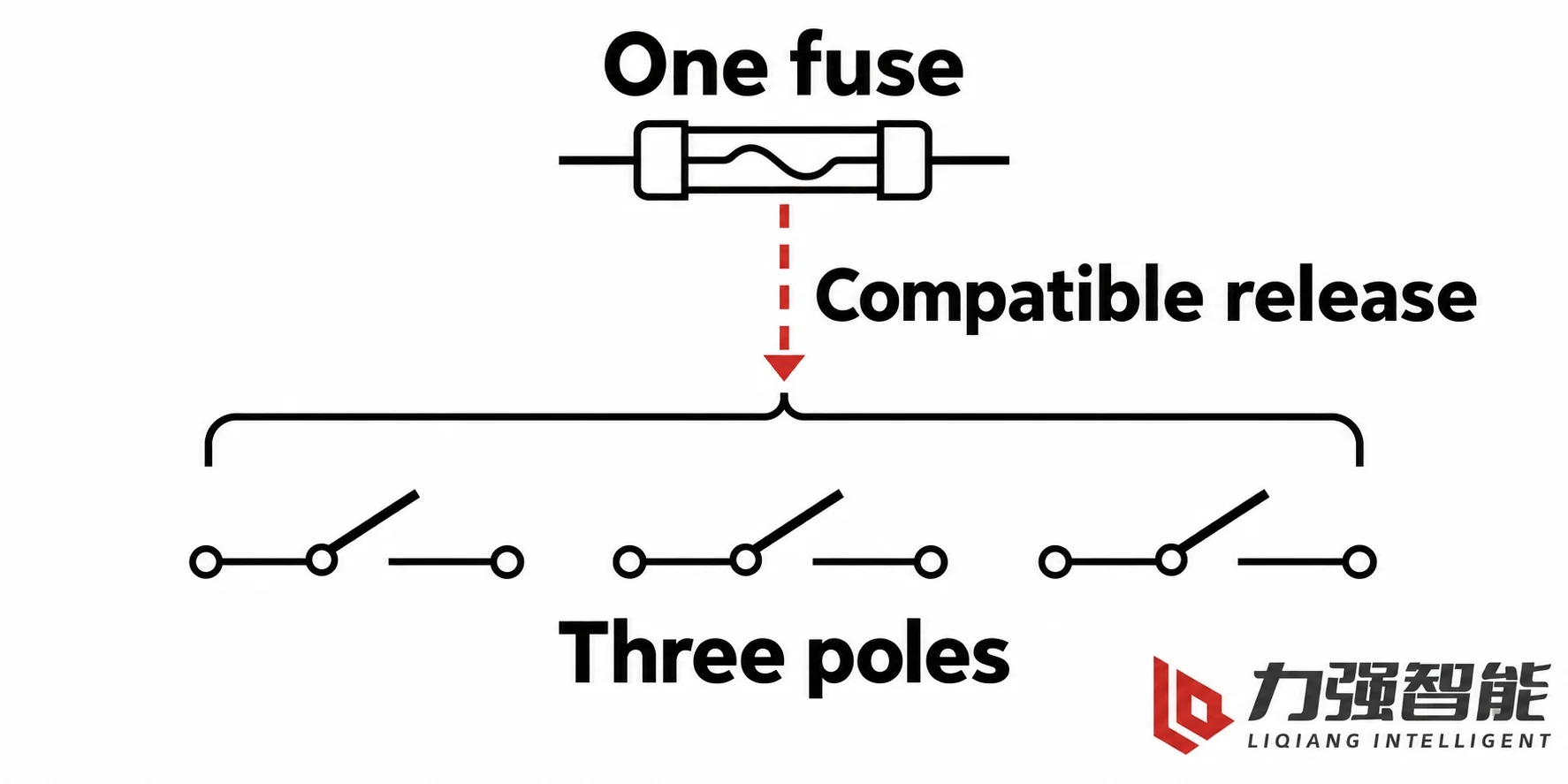
A fuse interrupting its assigned current and a fuse triggering a switch are different functions. Switch tripping requires the compatible striker and release arrangement.
The mechanical path is worth following in the actual FKRN construct. Liqiang’s FKN12/FKRN12 manual describes the operated fuse’s striker pushing on a trip lever, which releases the trip system and makes the switch open automatically. The switch itself is driven by a common main shaft, linkage and stored-energy mechanism, and the three-pole assembly drawing in that manual shows the structural relationship between the poles on that shared arrangement. The fuse element melts and its interrupting construction extinguishes the arc in its assigned duty. Fuse operation also causes the specified striker to act on the release, allowing stored opening energy to move the three switch poles. Fuse interruption and switch movement can overlap; their timing and current duties must work together in the coordinated arrangement.
That separation has two practical consequences. First, one operated fuse does not mean three fuses melted. The other fuse elements need not melt for their switch poles to open; the common mechanism supplies that movement. Second, the stored opening mechanism supplies the movement. The fuse does not mechanically carry the other poles open; it only triggers the release.
Opening all three poles matters because of what the alternative looks like downstream. A single cleared phase leaves the other two energised, and three-phase equipment — transformers, motors — connected beyond that point continues to see an unequal-phase supply, with the heating and voltage consequences that follow, while the circuit may look deceptively quiet to someone reading indicators. Common three-pole opening disconnects the supply through the three switch poles in that arrangement.
Not every version behaves this way, and the difference is in the configuration, not in the family name. ABB’s NAL/NALF catalogue describes fuse-base arrangements supplied with or without automatic tripping: a specified fuse-link striker can release the switch mechanism, and the two-spring mechanism described there holds stored opening energy in the closed position that can be released by hand, by an electrical command, or by the fuse striker. In that arrangement a blown-fuse indicator is not an opening command; indication and tripping are different functions, and producing the second requires the compatible trip interface, the correct fuse links and the specified mechanism. Whether a particular installation opens all three poles after a fuse operates is a question about the configuration that was ordered, not a general property of load switches or of fuses. And whether the switch then provides isolation or an earthed condition for the installation is a further question again, answered by the documented functions of that equipment rather than by the fact that the poles opened.
Operation of one specified compatible fuse can release the common mechanism and open the three switch poles; the other fuse elements need not melt for that movement.
Coordination: current, time and the devices on either side
A time-current characteristic describes how a protective device responds to different current magnitudes over time: an inverse-time response generally acts faster at higher current, while definite-time and instantaneous functions have different response shapes. Those characteristics, together with the interrupter’s clearing behaviour, affect which device completes interruption first for a given fault. Coordination is the exercise of comparing those characteristics, over the current range that matters, together with the topology — which devices actually see the fault current, through which series or parallel paths.
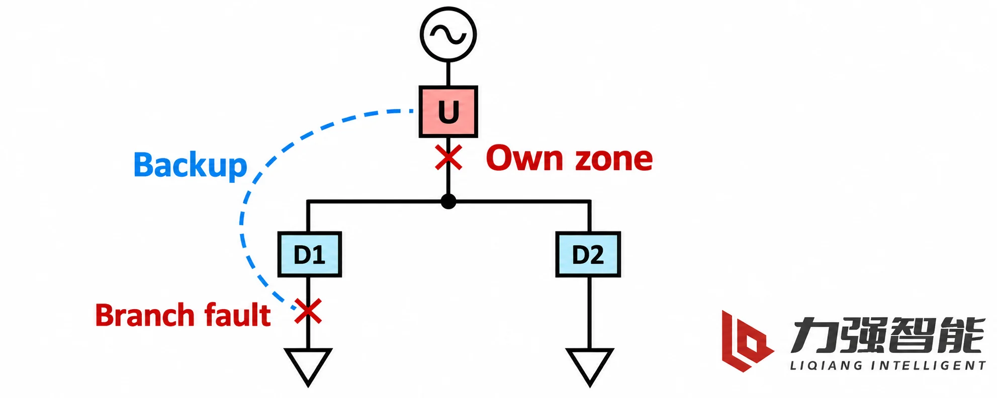
The purpose is easy to state and easy to get wrong. For a fault on a branch, the intended downstream response confines the outage to that branch while the rest of the system stays energised. That is selectivity. But selectivity is not the only requirement on the upstream device. It may protect connections or equipment ahead of the next protective device. In a radial arrangement, a fault there may not send current through that downstream device, so the assigned upstream protection must cover it. It may also provide assigned backup if downstream protection fails to clear. Low-current gaps need a function that actually detects and clears them; simply calling another device upstream does not fill those gaps. These own-zone and backup duties constrain how far operation can be postponed.
Two extremes therefore fail in opposite directions. Making every device as fast as possible can cause upstream protection to operate for a downstream branch fault before that branch clears, disconnecting healthy branches as well. If the upstream device is delayed indiscriminately to give every downstream device room, then upstream-zone faults, backup cases, and the thermal withstand of cables and transformers are all left waiting longer than they can tolerate: equipment withstand is a time limit as much as a current limit, and required fault clearing times come from the same study.
The presence of a relay, or of fuses, proves nothing about selectivity. It is the actual characteristics, on a common reference, over the required range, that support the conclusion. That range is also where a fuse and a breaker differ in character: a fuse’s response is fixed by the link chosen, while a relay characteristic can be shaped — which is exactly why the same coordination exercise produces different answers depending on which arrangement is in the feeder.
These are alternative fault locations in one radial topology. Upstream protection has its assigned own-zone duty and may provide assigned backup for a downstream branch, alongside the intended selective response.
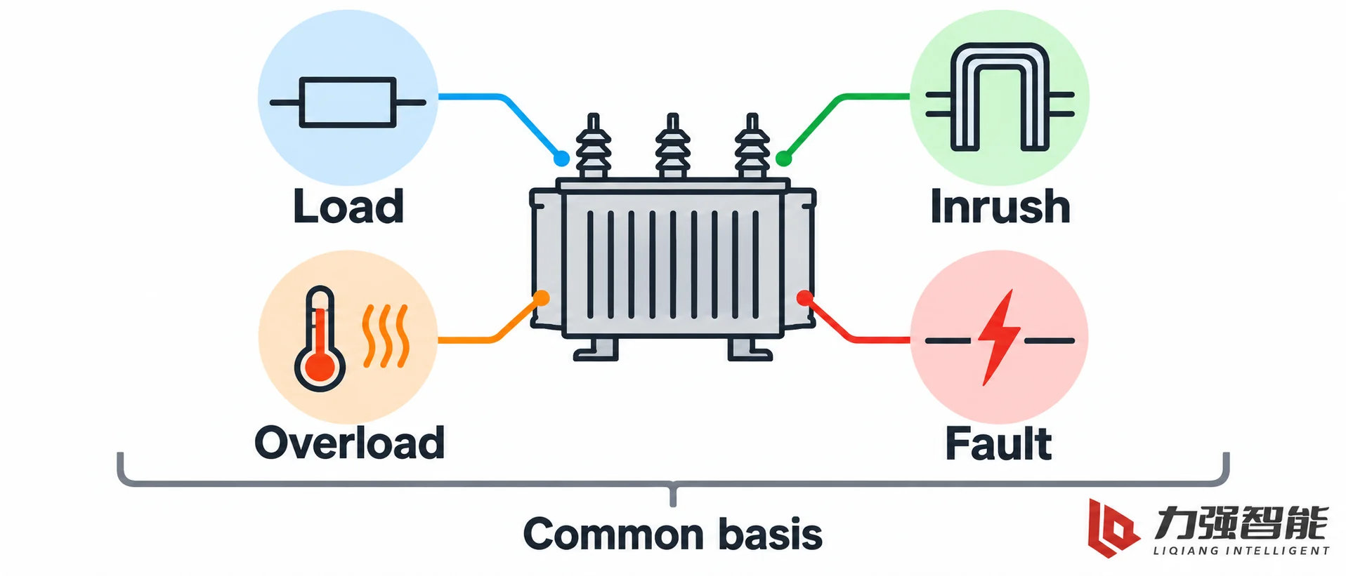
A transformer branch: load, energization, overload and fault are four different events
A transformer makes the difference between “high current” and “fault” concrete, because energization can produce a large magnetising transient in a healthy circuit.
Normal demand current is the intended loading condition. It may vary, and the protection must accommodate the assigned healthy-load envelope while retaining its required abnormal-condition response.
Energization inrush is a magnetising transient. When a transformer is switched on, the flux has to establish itself, and the magnetising current can rise well above its normal value before decaying. Its magnitude and duration depend on the energization conditions and transformer. Inrush in a healthy transformer is not a persistent circuit fault. It can be distorted and asymmetrical, so magnitude alone is a poor discriminator. Suitable response characteristics or detection principles must accommodate the assigned energization event while preserving fault response; a fault can also contain asymmetry or distortion.
Sustained overload exceeds the assigned loading envelope long enough to create excessive thermal stress. A maximum interrupting figure does not establish overload coverage. A fuse may interrupt below its current-limiting region, but only within its specified interrupting range; the selected response must still cover the required lower-current thermal events.
Fault current depends on source impedance, fault type and location. A high-current short circuit can impose severe thermal and mechanical stress, while lower-current faults also need the assigned detection and clearing coverage. Required clearing behaviour follows the protected equipment, fault conditions and system requirements.
Two engineering consequences follow. First, protection has to allow the assigned energization transient to pass while still responding within the limits set by damaging events and equipment withstand. That is done by selecting or configuring a characteristic whose shape and settings accommodate inrush in the current range where it occurs — not by applying a blanket delay to any high current, which would slow genuine fault clearing and eat into the withstand margins the system depends on. Second, things must be compared on the same reference. An upstream device’s characteristic and a downstream device’s rating only become comparable once both are expressed on a common voltage and current basis; a transformer’s ratio, a CT ratio, or an LV-side figure used unadjusted will produce a coordination study that looks complete and is wrong.
ABB’s official medium-voltage/low-voltage selectivity discussion uses a transformer supply example in exactly this spirit: inrush, load, fault, transformer withstand and the neighbouring and supply-side protection are considered together, with the supply-side device required both to cover the defined faults and to let the transformer energise. The example illustrates the reasoning; the actual curves and equipment limits are project data.
This is also where the fuse’s boundary becomes visible in project terms. A fuse with a high interrupting capability can be entirely correct for the fault duty and still not cover low-current overload, because that duty lies outside the region where it is intended to act. Where the selected fuse or combination does not cover a required low-current duty, an appropriate additional protection function must provide it. That can involve a suitable relay or another coordinated device, but its sensitivity, location and response must match the event.
Load, energization inrush, sustained overload and faults present different protection tasks. Compare the relevant characteristics and equipment limits on a common voltage and current reference.
Choosing an arrangement for a given feeder
Consider an indoor installation with a distribution transformer fed through a suitable switchgear branch. The branch duty is defined and stable, the load current is modest, the fault level at the branch is within the range a compatible switch-fuse combination is rated for, and the operating need is simple: switch the transformer in and out, and let the branch be cleared if a fault develops. That is the natural home of a coordinated switch-fuse combination — for example the FKN12-12 switch in its FKRN12 switch-fuse arrangement, with the specified current-limiting fuse links and the striker-operated tripping described in the manual. The consequences are part of the choice: the fuse’s response is fixed by the link that is installed, so the characteristic is set at selection time; fuse operation consumes the operated link and creates a need for the specified replacement and service response; measurement and configurable protection functions are limited to what the arrangement provides; and the installation depends on the correct specified links being available and on the striker interface being the compatible one.
Now change one condition. Suppose the same substation has a main incoming or outdoor feeder that has to coordinate with several downstream branches, needs configurable overcurrent and possibly other configured protection functions, is controlled remotely, and needs fault duties and coordination suited to each equipment position. Those requirements point the other way, towards a measured arrangement: current information, a protection relay with the functions the feeder needs, a trip path with dependable control supply, and a breaker with the required breaking capability. Indoor, that is the kind of task the VS1-12 serves; outdoors, where the switching device has to live in the feeder rather than in a switchgear room, the ZW32-12 is a relevant outdoor breaker family to consider. The consequences are symmetrical to the fuse case: the protection is adaptable and can be re-coordinated as the system changes; breaker opening does not normally consume a fuse link, while subsequent service depends on the device and event; the arrangement depends on the specified trip-energy path, on settings that are actually determined and checked, and on the breaker’s breaking capability covering the prospective fault current at that point.
These are tendencies driven by requirements, not a ranking. Branch duties that are defined and modest, where a fuse characteristic fits the one job the branch has to do and where a compatible tripping arrangement is available, suit the combination. Duties that need configured detection, coordination with neighbours, measurement, or remote operational control favour the relay-and-breaker arrangement. Many real feeders combine both — a breaker at the incomer and fuses downstream — and any additional function, such as sensitive earth-fault detection or directional elements, belongs to whichever scheme actually includes it and not to the comparison in general.
If you are working through a specific feeder, the relevant next steps are the equipment documents rather than a generic comparison. The FKN12 load-break switch and switch-fuse family page covers that configuration route, the load-break switch family covers the wider range including the vacuum load-switch models, and the indoor and outdoor vacuum circuit breaker families carry the breaker arrangements. Manuals and interface documents are collected in Downloads. For the meaning of the individual rating fields — breaking, making, short-time withstand, and how they relate to each other — see the medium-voltage switching device ratings explanation, and for the full device and project selection exercise, including the information a supplier needs, see how to select medium-voltage switching devices.
FAQ
Does a blown-fuse indicator prove that all three switch poles opened?
No. Indication reports a condition; common opening requires the specified fuse striker, compatible release and operating mechanism. The other fuse elements do not have to melt for their switch poles to open, because stored mechanical energy supplies that movement. Whether a version provides this response follows from its actual configuration. Three-pole opening also does not by itself establish isolation or an earthed installation.
Does upstream protection automatically cover currents below a fuse’s operating range?
No. The additional function must detect the required event at its actual measurement location and clear it within the protected equipment’s limits. Calling a device upstream does not establish its sensitivity, coverage or response time. The selected fuse’s interrupting range, the required low-current protection and the assigned upstream own-zone or backup duties must fit the same feeder arrangement.
Why can transformer energization need a different protection response from a fault?
Energization can produce a large, distorted magnetising transient in a healthy transformer, while a fault can also contain distortion or asymmetry. Magnitude or waveform appearance alone therefore does not settle the distinction. The selected protection must accommodate the assigned inrush event while retaining the required fault response and equipment withstand margins. A blanket delay on every high-current event can undermine those duties.
Share your love
William Xiaonan Liu
William Xiaonan Liu writes for LIQELE about medium-voltage switching equipment, including vacuum circuit breakers, load break switches, disconnectors and earthing switches. His articles explain product selection, installation interfaces, operating requirements and technical documentation, helping switchgear builders and project buyers identify the information needed for equipment selection and supplier discussions.