What Is a Load Break Switch? Switching Duties, Types and Limitations
Approx. 13 min read
Quick Takeaway
A load break switch carries normal current and performs its assigned load-switching duties. Active loads, unloaded transformers, charging currents and closed-loop switching impose different interruption conditions; carrying current alone does not establish all of those capabilities.
Air-blast and vacuum describe ways to control an arc, while embedded-pole and middle-mounted describe other parts of the equipment. None of these labels alone establishes short-circuit breaking, isolation, earthing or cabinet compatibility.
In a documented switch-fuse combination, the switch and specified fuse divide their assigned duties. A compatible fuse striker can release the switch mechanism, but physical fuse fit or a standalone fuse rating does not establish the complete arrangement’s coordination.
A load break switch is a mechanical switching device whose closed contacts carry a circuit’s normal current and whose assigned switching duty is to connect and interrupt load current under stated conditions. In a distribution circuit that duty is concrete: energising or de-energising a transformer branch, splitting or re-paralleling a network section, or taking a loaded cable feeder out of service. What a bare load break switch is not is a complete fault-protection arrangement — fault clearing is provided by the protection assigned to the circuit, such as a documented coordinated switch-fuse combination or a circuit breaker.
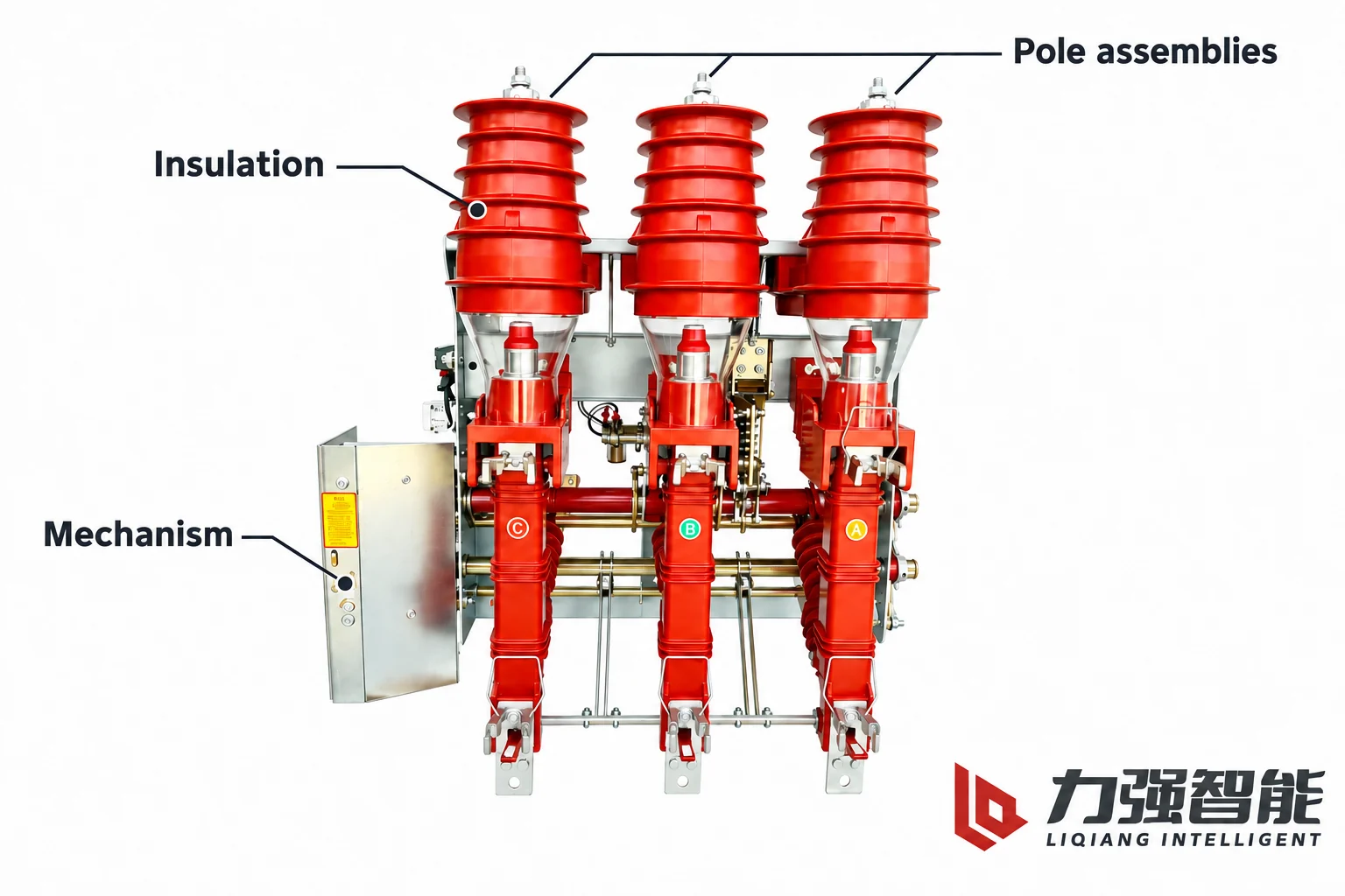
A complete load-switch assembly brings together pole groups, conducting connections, an operating mechanism, insulation and a supporting frame.
What a load break switch does in a distribution circuit
When the switch is closed, its contact system is simply a section of the conducting path, carrying whatever current the connected circuit draws. The device lets operators make controlled changes to the circuit connections during normal service. A distribution network has many nodes where current must be made and broken as part of ordinary operation: a transformer branch feeding a plant is disconnected while it carries its normal load; a documented ring or loop arrangement is sectionalised according to its assigned switching duties; a cable or overhead line is taken out of service and its charging current interrupted. Each of those actions is an assigned load-switching duty, and each has to be performed repeatedly, safely and predictably.
That is why the term load break switch describes a duty rather than a single performance number. The documented switch has a set of assigned switching purposes — typically including mainly active load, closed-loop current, unloaded-transformer switching, and cable or line charging current — and the contact system with its arc-control arrangement is built to make those interruptions repeatable. Fault clearing is a separate matter: a bare switch interrupts the load current assigned to it, while the short-circuit duty of a transformer branch normally belongs to a specified current-limiting fuse inside a coordinated combination, or to a circuit breaker further upstream.
Contacts, mechanism and arc control work together
An interruption only becomes possible because several sets of parts cooperate, and the supplied FKN12 manual separates them clearly. The static contact, the moving contact and the conducting tube form the current-carrying and interrupting path. The drive shaft and insulating pull rods transmit motion to those parts, and a spring stored-energy mechanism supplies the energy for the operation itself. The frame carries the insulating supports and contact assemblies and passes mechanical reaction forces into the installation.
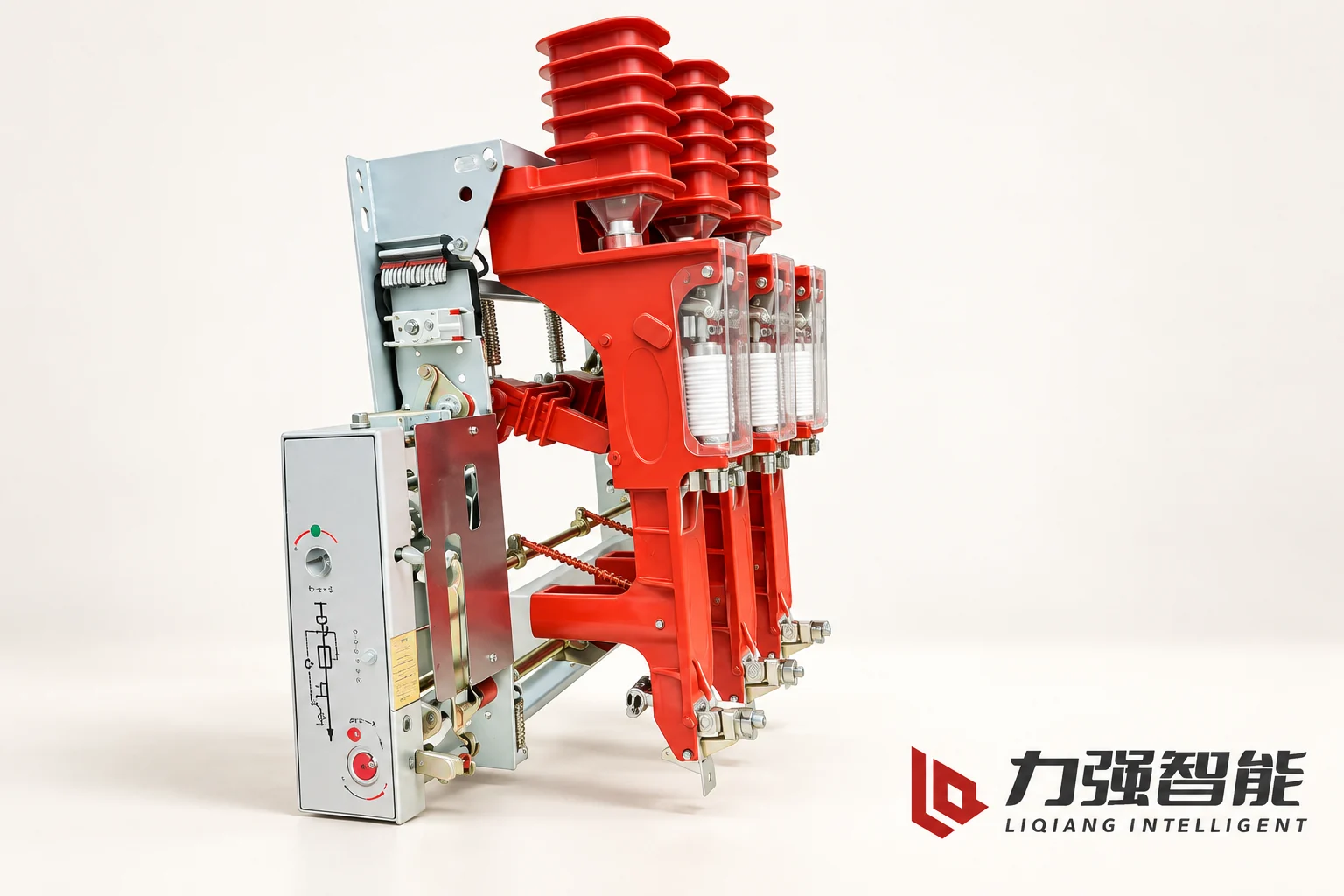
The FKN12 reference photograph identifies the major external groups: three-phase insulated contact assemblies, the mechanism housing and the shared structure. The manual explains the hidden arcing contacts and their operating relationship.
The arc is the reason an interruption arrangement is needed at all. When two current-carrying contacts part, the gap between them is not yet an interruption: an arc can form as the current-carrying contacts separate and can remain a conducting path, so current does not necessarily cease with the contact movement. The interruption arrangement therefore has two jobs. It must act on the arc so the current is extinguished, and it must then keep the separated gap able to withstand the voltage that reappears across it. Contact travel, opening speed, nozzle or interrupter geometry and the recovery behaviour of the interrupting medium all serve one or the other of those jobs. The operating mechanism supplies controlled contact motion. Insulation and the support structure maintain the required electrical separation and mechanical alignment. The contact and arc-control system performs the assigned current interruption.
The pole groups, insulating surfaces and operating mechanism have distinct roles within the complete switch assembly.
Air-blast and vacuum are two ways to manage the arc
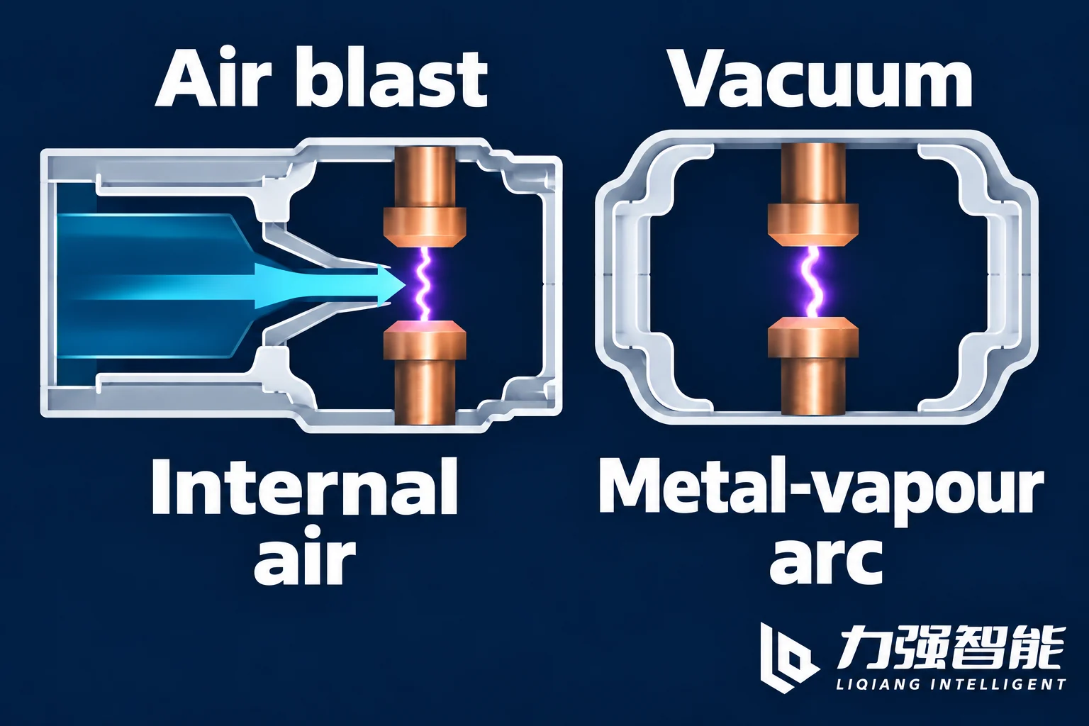
In the supplied FKN12 design, the arc is handled by air compressed inside the switch itself. As the contacts and the conducting tube move apart during opening, that movement compresses air within the pole, and the compressed air is directed through a nozzle toward the arc region and the arcing contacts, where it disturbs and cools the discharge until it ceases. The sequence is worth noting: separation creates the conductive arc path first, and the air blast then acts on that established arc. The pressure comes from the switch’s own internal mechanism, not from an external compressor, receiver or pipework feeding the switchgear.
The supplied FZN25 arrangement takes the other route, placing its interrupting contacts inside a vacuum interrupter. A common assumption is worth correcting here: opening contacts in vacuum does not mean there is no arc. The arc burns in metal vapour drawn from the contact surfaces and continues to conduct while the alternating current flows. What makes interruption possible is the alternating current itself. In successful AC interruption, the arc extinguishes around a current-zero opportunity, the metal vapour condenses and the separated gap recovers dielectric strength. The recovering gap must withstand the voltage that rises across it. The interruption is completed around the current zero, not simply by the movement of the contacts.
Neither approach is a general ranking. Air-blast and vacuum describe how the arc is dealt with, and both exist to make an assigned load interruption repeatable. They do not, by themselves, state what an arrangement is permitted to break, how a complete assembly behaves inside a particular cabinet, or which technology is the right answer for a given project.
The air-blast example directs internally compressed air at the arc. The vacuum example uses a sealed chamber, where contact metal supplies the arcing vapour before successful interruption.
Why the nature of the load changes the requirement
Load switching is not one universal duty, and product documents treat it as several. The supplied FZN25 manual lists load current, closed-loop current, unloaded-transformer switching and cable charging current as distinct purposes. The FZN64 material goes further and separates, in its own fields, mainly active load, closed-loop duty, cable and line charging, a specified earth-fault breaking duty, transfer current, short-time withstand and making. The reasons that field list is so long are electrical, not administrative.
With mainly active load, current and voltage are closely in phase, so the recovery-voltage conditions at current zero differ from reactive-load duties. An unloaded transformer draws a small but inductive current; early current extinction can leave stored magnetic energy that produces transient voltage stress. In cable or line charging duty, current leads voltage. The circuit can retain charge after interruption while the source voltage continues to change, and the recovering gap must withstand that voltage difference. Restrikes can lead to further voltage escalation. In closed-loop duty, the switch interrupts current in one path of an interconnected network. Opening that path redistributes current, and the recovery voltage depends on the surrounding network.
Two consequences follow for reading a specification. A rated current value is a statement about carrying current through closed contacts, not a licence to interrupt every load of that magnitude under every condition. And a separately listed duty such as a specified earth-fault breaking capability is exactly that — an assigned condition inside the documented range, not a general short-circuit rating.
The switch and fuse are a coordinated arrangement
Liqiang’s manuals keep the bare switch and the combination apart by designation. FKN12 is the load switch and FKRN12 the switch-fuse combination; FZN25 and FZRN25 follow the same pattern; FZN64 and FZRN64 likewise. The VZFR-12 object described in the VZF-family manual is a middle-mounted, embedded-pole vacuum combination in which the vacuum switch body and the current-limiting fuses share one series circuit and divide their assigned duties: the switch performs the stated load switching and the breaking duties within its documented range, while the current-limiting fuse performs the stated short-circuit breaking, and the same description also refers to overload and the corresponding short-circuit range. Read that as a coordinated division of labour inside a defined range — not as a statement that the fuse handles every fault-related event on its own, and not as permission to pair an arbitrary fuse with an arbitrary switch.
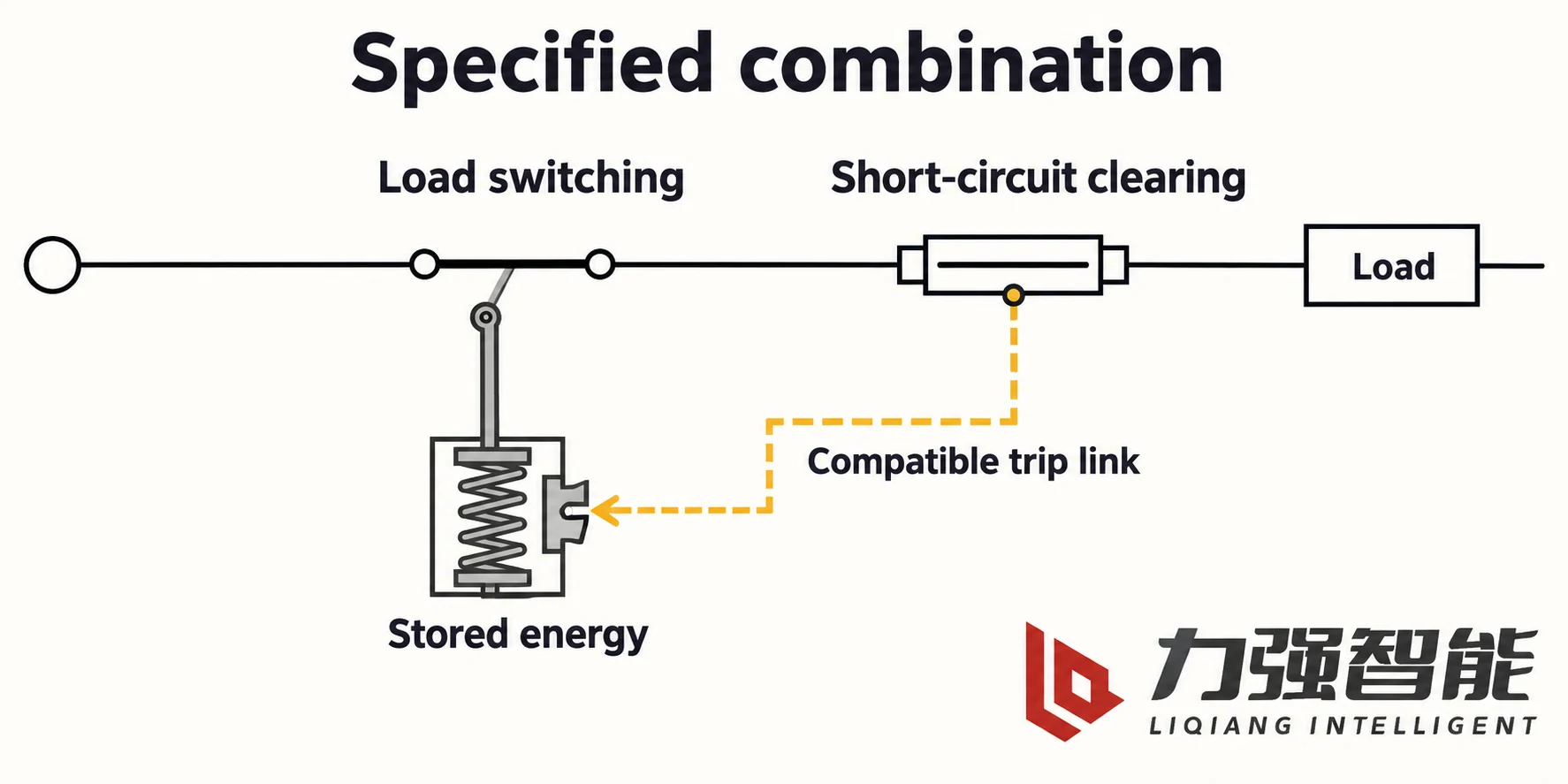
The FKN12 material also describes the mechanical link between the two components, and it is worth following the chain in order. When the fuse operates, its striker pushes the tripping lever; the lever turns the tripping shaft and linkage; that releases the stored energy of the switch mechanism, and the load switch opens automatically. Two practical points follow. The energy that opens the switch comes from the switch’s own stored-energy mechanism — the fuse only triggers it. And the behaviour exists only where the arrangement includes every link: a fuse of the type whose striker output matches the release, a fuse base that includes the tripping release, and the combination version of the switch. FZN64’s fuse selection guidance states the striker-compatibility requirement explicitly, and the ABB NAL/NALF example shows the same logic from the other direction: its fuse base can be supplied with or without automatic fuse-striker tripping, and its combination ratings are bound to specified reference fuse links. A fuse that fits the holder but has the wrong striker characteristic does not reproduce the chain.
This is also the place to keep four duty words apart. Carrying describes current flowing through closed contacts. Load-breaking describes interrupting the assigned load under the stated conditions. Making describes establishing current during closing, including a short-circuit making duty where assigned. Short-time withstand describes enduring the specified current for a stated duration; peak withstand concerns the specified peak-current stress. None of those is short-circuit breaking: the fault-interruption duty belongs to the combination, inside the range documented for the specified switch and fuse together, and it is not created by joining a switch rating and a standalone fuse rating.
Within a specified combination, the switch serves load switching and the fuse its assigned short-circuit clearing duty. A compatible striker link releases the switch's stored-energy mechanism.
Type labels describe different parts of the equipment
Descriptions of load switches tend to stack several labels onto one product, which is why they are so easily misread as grades. In fact the labels come from different axes, and the same device can carry all of them at once.
Label
What it describes
What it does not settle
Air-blast, vacuum
How the arc is managed at interruption: air compressed by the contact motion and directed at the arc in FKN12, a vacuum interrupter in FZN25
The assigned switching duties or the breaking ratings of the arrangement
Embedded pole
The external structure and insulation: the vacuum interrupter and connecting parts encapsulated inside a resin pole
The interruption medium, or the cabinet interface
Middle-mounted
The cabinet and installation layout
Any performance grade
VZFR-12 is a useful example precisely because it carries all three at once: vacuum interruption inside embedded poles, in a middle-mounted cabinet arrangement. FKN12 and FZN25, by contrast, distinguish two interruption methods — air-blast and vacuum — while sharing the general construction logic of contacts, mechanism, frame and insulating supports.
A closely related label is switch-disconnector. Where the documented arrangement provides both load switching and an isolation function, that name describes the combined duty, and manufacturers list the two functions separately rather than assuming one from the other; the ABB NAL/NALF example, for instance, separates load-switching and isolation functions, the frame, insulation and current-carrying parts, the mechanism, and the auxiliary functions. The distinction is real inside a single product too: the FZN25 arrangement identifies a separate isolating part alongside the vacuum interrupter, with isolation upper and lower contacts named as objects distinct from the interrupter itself. So load switching and isolation can coexist, but the load switch name alone promises neither isolation nor earthing. Both are documented functions of a particular arrangement, and earthing is a third function again that many load switches do not include at all.
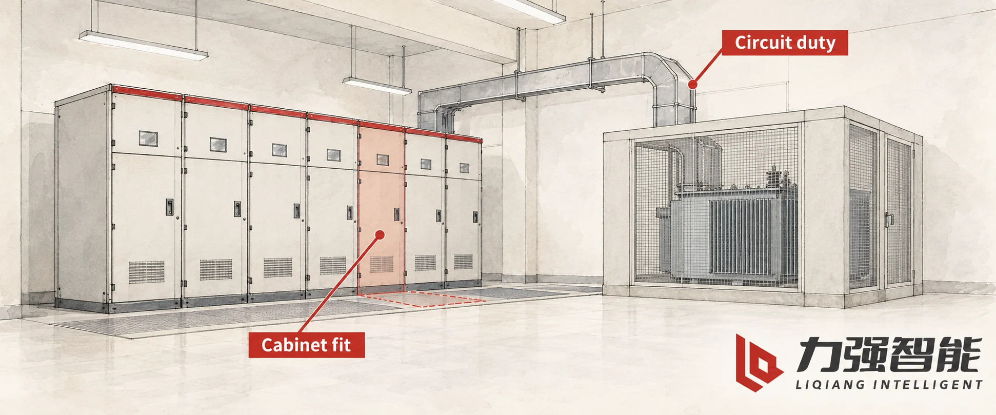
Transformer-branch duties and the cabinet's physical interfaces are separate inputs when assessing a load-switch arrangement.
Matching the load-switch arrangement to the circuit
The choice between arrangements follows from the circuit and the cabinet, not from a technology ranking. A few conditional cases show how the reasoning runs.
Consider an indoor project adding a transformer branch to a switchgear lineup that already uses the air-blast switch-fuse arrangement. The requirement is ordinary: switch the transformer branch under load, and provide the branch with coordinated fuse protection for its short-circuit duty. If the existing cabinet’s mounting, panel opening, operating access and fuse-base geometry already match that qualified arrangement, then retaining it is the natural answer — not because air-blast is technically superior, but because the interfaces and the documented combination already line up and the assembly’s duties are already established for that layout.
Change the conditions and the answer changes. If the same project is specified with a new middle-mounted cabinet and an embedded-pole design, then the layout itself is part of the requirement, and the matching documented object is the vacuum combination with embedded poles in a middle-mounted arrangement. Vacuum interruption is not the reason for the choice in that case; the reason is that the specified cabinet and pole construction call for that configuration, and a differently built switch would raise mounting, access and interface questions. Every candidate still has to satisfy the circuit’s required switching and protection duties.
A third case is a network section that needs its assigned switching duties performed — sectionalising a documented loop arrangement — with protection already provided by a breaker elsewhere in the lineup. There, the object under review is the switching device itself, with its documented duties and, where the arrangement provides it, its isolation function. Adding a fuse combination would not be justified by the duty, and no fault-clearing role should be written into it.
The fourth case is the one that forces a change of architecture: where the prospective short-circuit level at the point of installation, or the grading required with upstream protection, exceeds what the documented combination covers. The answer there is not a larger generic fuse, a different bare switch, or an assumption that the fuse will manage it anyway. The combination’s rating is tied to the specified fuse and to the striker and release arrangement, so the next step is to reassess the feeder architecture — a circuit breaker, or a different combination — using the coordination material rather than extending the load switch by argument.
Is a load break switch’s rated current also its short-circuit breaking rating?
No. Rated current describes carrying current through closed contacts. The assigned load-breaking duties describe particular switching conditions, while making and withstand ratings describe different stresses. A short-circuit breaking duty must be established for the documented protective arrangement; it cannot be inferred from a bare switch’s current, making or withstand rating.
Does every load break switch also provide isolation?
No. Load switching and isolation are separate functions. A documented switch-disconnector can provide both, and some vacuum arrangements include a separate isolating part alongside the interrupter. The load break switch name alone does not establish an isolation function or an earthing function for the device being considered.
Can a fuse be replaced with any other fuse that fits the holder?
Physical fit is insufficient for a switch-fuse combination. The specified fuse characteristics and the combination’s documented duties must remain compatible. Where a striker initiates switch opening, its output must also match the release arrangement. A different fuse can alter protection coordination or fail to reproduce the intended tripping behaviour even if it fits the base.
Share your love
William Xiaonan Liu
William Xiaonan Liu writes for LIQELE about medium-voltage switching equipment, including vacuum circuit breakers, load break switches, disconnectors and earthing switches. His articles explain product selection, installation interfaces, operating requirements and technical documentation, helping switchgear builders and project buyers identify the information needed for equipment selection and supplier discussions.